
CLAAS Mercedes-Benz OM 470 LA OM 471 LA Diesel Engine Repair Manual 00 0300 667 0 (May 2015)
Original price was: $34.95.$20.95Current price is: $20.95.
CLAAS repair manual 00 0300 667 0 (May 2015) for Mercedes-Benz OM 470 LA, OM 471 LA and OM 473 LA diesel engines, covering housing, running gear, cylinder head, common-rail fuel system, lubrication, cooling, exhaust aftertreatment and special-tool procedures.
Description
CLAAS Mercedes-Benz OM 470 LA OM 471 LA Diesel Engine Repair Manual 00 0300 667 0 (May 2015)
This CLAAS Mercedes-Benz OM 470 LA OM 471 LA Diesel Engine Repair Manual 00 0300 667 0 (May 2015) is the Service & Parts workshop book for the Mercedes-Benz in-line six-cylinder engines used in CLAAS harvesting equipment. The validity table names three type designs: OM 470 LA type 470.907 with engine numbers 470.907-C-xxxxxx, OM 471 LA type 471.919 with engine numbers 471.919-C-xxxxxx, and OM 473 LA type 473.905 with engine numbers 473.905-C-xxxxxx. All three series are listed at TIER 4 / Stage IV exhaust-gas level. Picture sequences show the repair steps; the text supplies the adjustment values, special-tool numbers and tightening data needed to complete each job.
File Details
- Manual type: Repair manual (RHB Dieselmotor OM470/471LA)
- Brand / engines: CLAAS / Mercedes-Benz OM 470 LA, OM 471 LA, OM 473 LA
- Language: English
- Page count: 504
- File format: PDF
- Document number: 00 0300 667 0
- Date: May 2015 (05/2015)
Engines Covered and Basic Engine Data
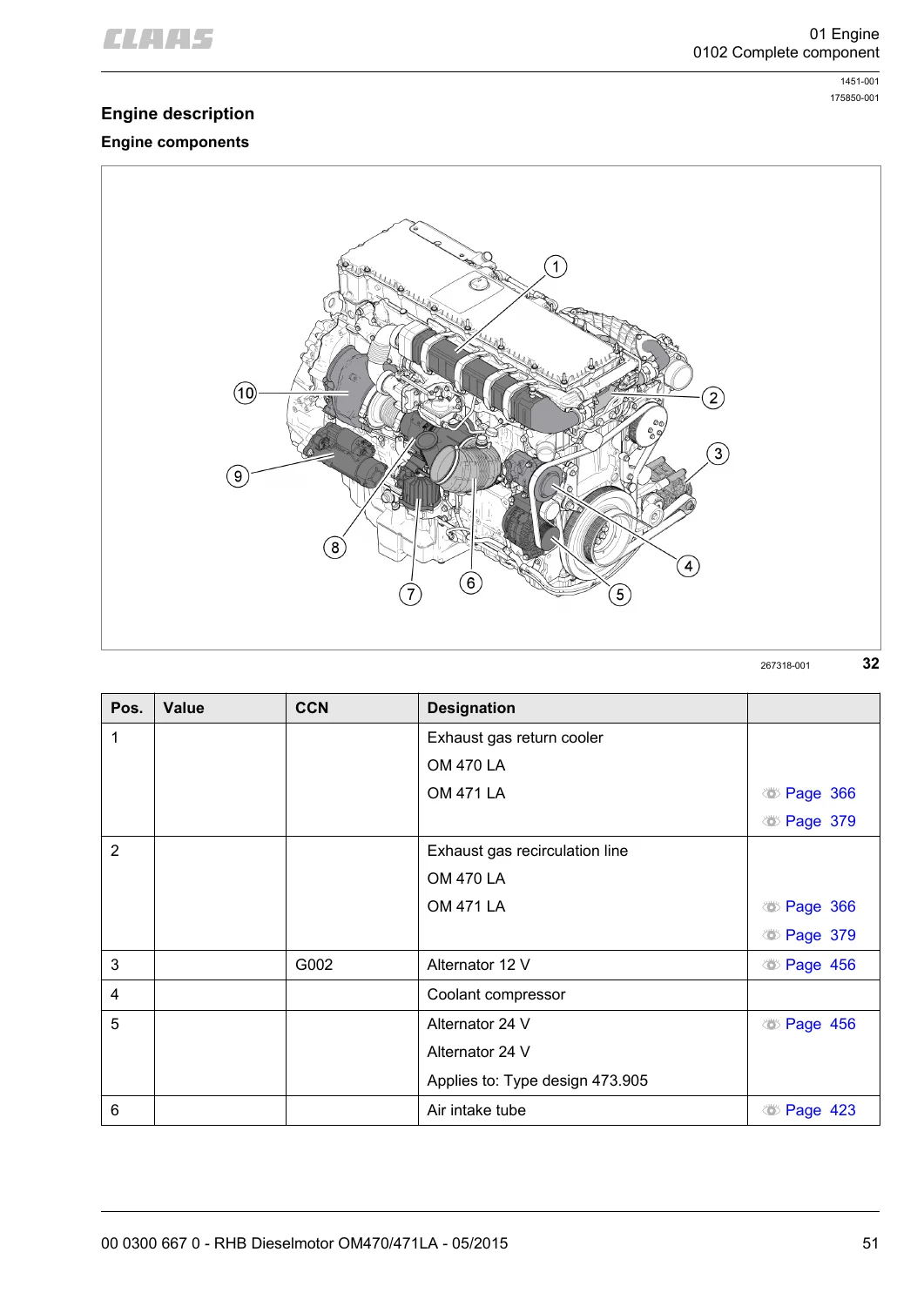
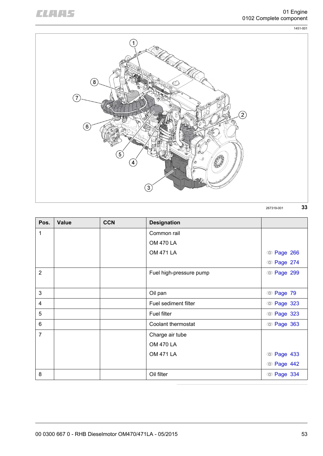
The opening engine chapter records the hardware identity of each series so the technician can confirm the block on the stand before tearing it down. The OM 470 LA is an in-line six with a 125 mm cylinder bore, 145 mm stroke and 10700 cm³ cubic capacity; dry weight is given as 990 kg. The OM 471 LA uses a 132 mm bore and 156 mm stroke for 12.800 cm³ and weighs 1140 kg. The OM 473 LA uses a 139 mm bore and 171 mm stroke for 15.600 cm³ and weighs 1277 kg. On all three engines the direction of rotation when viewing the flywheel is left. Component maps identify the exhaust-gas return cooler, recirculation line, 12 V and 24 V alternators, oil separator, exhaust turbocharger, electric starting motor, turbo compound unit, common rail, fuel high-pressure pump, oil pan, fuel sediment filter, fuel filter, coolant thermostat, charge-air tube and oil filter.
Sensor locations are called out by CLAAS Component Number: camshaft position sensor B601-MB, crankshaft position sensor B600-MB, combined oil level / temperature sensor B605-MB, fuel temperature sensor B602-MB, charge-air temperature sensor B617-MB, fuel-filter module pressure sensor B638-MB, charge-air pressure and temperature sensor B608-MB, rail pressure sensor B622-MB, coolant inlet temperature sensor B607-MB, oil pressure sensor B604-MB, exhaust-gas recirculation differential pressure sensor B621-MB and coolant outlet temperature sensor B606-MB. Actuators in the same maps include injectors, the fuel controller valve Y642-MB, charge-pressure actuator Y636-MB and the exhaust-gas recirculation actuator.
Workshop Practice, Safety and Torque Data
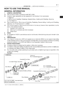
General repair instructions open the book before any engine-specific chapter. Surfaces must stay clean; rotating parts are marked before removal so they go back on the correct side; expansion-pin slots face the loaded side; cotter pins, lock washers and spring washers are replaced; different oil grades are not mixed. Self-locking bolts must not contact sealing compound and are tightened quickly to the listed torque. Liquid locking compound is used only where the procedure names it, on grease-free faces, and a glued joint can be released by heating to about 200 °C. Separate notes cover steel roller-chain tension, chain-connector orientation, taper-ring fasteners, gib-head keys, lock-collar and adapter-sleeve bearings, chuck bushings, circlips, ferrule fittings, sealing-cone fittings and hydraulic-hose routing and age limits.
The safety chapter uses DANGER, WARNING and CAUTION signal words. Testing, adjusting and repair work is stated as work for CLAAS sales partners, and the machine repair manual must be used together with this engine book. Hands stay out of pre-loaded components; the battery isolating switch is opened when the engine is still in the machine; hot fluids and rotating parts are allowed to cool. Spare-part guidance recommends genuine CLAAS parts and asks for the machine identification number when ordering.
A dedicated torque section lists metric standard and fine-thread values at friction coefficient μ tot = 0.14 for strength classes 8.8, 10.9 and 12.9, plus tables for hydraulic screw fittings with sealing cone and O-ring (DIN 3865), ferrule fittings (DIN 3861), SDS male connectors in several sealing shapes, hydraulic swivel fittings, hollow screws DIN 7643 and direction-adjustable SDE connectors. Engine-specific multi-stage torques sit in the component chapters: connecting-rod bolts on the OM 470 LA at 150 Nm then 90°; piston bolts at 150 Nm (OM 470 LA) or 180 Nm (OM 471 LA) then 90°; cylinder-head screws at 50 Nm, then 100 Nm on the OM 470 LA or 200 Nm on the OM 471 LA, then 90° and another 90°. Shaft-length limits for cylinder-head screws on the OM 470 LA are 186 mm new and up to 188 mm permitted.
Special Tools, Cranking and Timing Marks
Cranking can be done by hand with the engine still installed or after it has been lifted out. Common tools include cranking tool 00 1992 902 0, template 00 1998 587 0 and punch 00 1998 572 0. For in-chassis work the special-tool kit 00 0181 932 0 is paired with machine-specific adapters. The built-in tables name CLAAS JAGUAR type 496 and type 497 and LEXION C68, C74, C75, C76, C77, C78 and C79, matching each machine to OM470LA, OM471LA or OM473LA and to the required cranking tool, thread adapters, spacer tubes, hex bolts, washers and set screws.
Setting ignition TDC uses the flywheel mark against the cast edge on the timing housing, then a template whose designations must line up with the outlet-camshaft gearwheel: 10.6 on the OM 470 LA, 12.8 on the OM 471 LA and 15.6 on the OM 473 LA. If a reinforcing frame is fitted on the OM 470 LA or OM 471 LA the spacer is omitted. A locking pin through the B600-MB sensor bore holds the flywheel while timing work proceeds. Other numbered tools appear throughout the book: piston-ring compressor 00 0147 999 0, cylinder-liner removal and installation tool 00 1998 590 0, valve toolbox 00 1998 591 0, injector extraction tool 00 1998 577 0 and installation tool 00 1998 589 0, EGR leakage-test device 00 1998 593 0 with pressure pump 00 1998 565 0, oil-filling adapter 00 1992 893 0 and oil filling container 00 1992 872 0.
Chapters Covered
- Introduction — General information; General repair instructions; Torque settings
- CCN explanation — CLAAS Component Number electric-system letter codes
- Safety — Hazard signs, signal words and workshop rules
- 0102 Complete component — Type designs, engine data, component and sensor maps, cranking, TDC setting
- 0105 Engine suspension — Lifting eyes and mount hardware
- 0110 Engine housing — Oil pan, crankshaft front and rear seals, housing cover, timing housing, oil separator
- 0115 Engine unit — Piston and rings, connecting rod, cylinder liner, crankshaft, oscillation damper, flywheel
- 0120 Cylinder head / Valves / Idler gear — Valve cover, reinforcing frame, camshaft housing, camshaft, cylinder head (separate OM 470 LA and OM 471 LA procedures), outlet rocker arm mechanism, valves, valve springs and stem seals, gear drive
- 0125 Injection- / Fuel system — High-pressure lines and rail, rail pressure relief valve, injectors, protective sleeve, fuel high-pressure pump, 2-step valve, fuel pump, pressure relief valve, fuel controller valve, fuel filter module
- 0130 Lubricating oil system — Oil spray nozzle, oil coolant module, oil cooler, oil pump, oil thermostat
- 0135 Cooling system — Coolant pump, coolant thermostat
- 0140 Exhaust system — Exhaust-gas return cooler, recirculation actuator, differential pressure sensor, exhaust manifold, exhaust turbocharger
- 0145 Air intake — Charge-air housing and related sensors
- 0150 Engine attachment parts — Electric starting motor, alternator, resonance vessel, air compressor
- 0155 Engine control — Control unit
- 0165 Exhaust gas aftertreatment — Exhaust treatment system, urea heater valve, urea pump and inlet-nozzle filter
- Index
Taken as a whole, the CLAAS Mercedes-Benz OM 470 LA OM 471 LA Diesel Engine Repair Manual 00 0300 667 0 (May 2015) is a complete in-frame and out-of-frame rebuild guide rather than a quick-reference booklet. Each assembly chapter pairs a technical-specification table (torques, CCN codes, wear limits) with removal, inspection and installation steps and with the special-tool callouts required for that job.
Running Gear, Cylinder Head and Valve Gear
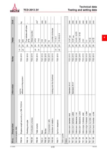
Housing work covers oil-pan removal, crankshaft radial seals (including the dedicated OM 471 LA front-seal driver and spacer washer), timing-housing service and the oil separator. Piston service includes ring height play and push play: on both OM 470 LA and OM 471 LA, ring (4) height play is 0.057 mm to 0.103 mm and ring (5) is 0.047 mm to 0.093 mm; push play is 0.30 mm to 0.45 mm on ring (3) and 0.70 mm to 0.90 mm on ring (4). Connecting-rod bushing inner diameter on the OM 470 LA is 55.070 to 55.080 mm against a piston-pin outer diameter of 54.994 to 55.000 mm, giving radial pin clearance of 0.070 to 0.086 mm. Connecting-rod bearing inner diameter (shells fitted) is listed in standard and 0.25 / 0.50 undersize steps, with radial connecting-rod play 0.057 to 0.122 mm on the OM 470 LA.
Cylinder-liner protrusion is 0.140 to 0.270 mm, with a maximum 0.09 mm difference between protrusions on one liner. Bore diameter is 124.990 to 125.010 mm on the OM 470 LA and 131.990 to 132.010 mm on the OM 471 LA. Crankshaft work on the OM 471 LA includes thrust measurement with a clock gauge and bearing-cap pullers; connecting-rod pin diameters are given in standard and deviation sizes. Valve depth is 0.7 to 1.1 mm on both OM 470 LA and OM 471 LA; installed valve-guide inner diameter is 9.500 to 9.522 mm. Rocker-arm service uses a fixing device so the shaft can be tipped out without losing the spacer-ring order marked TOP, FRONT and TOP, REAR. Valve-clearance checks are tied to tabulated crankshaft positions for OM 470 LA / OM 471 LA / OM 473 LA.
Fuel, Oil, Coolant, Air and Aftertreatment
Common-rail chapters split the high-pressure lines and rail between the OM 470 LA and the OM 471 LA so union-nut torque and bracket orientation stay correct. Injector clamps on all three engines tighten in two steps: 20 Nm then 90°. Protective sleeves are drawn and refitted at 50 Nm. The high-pressure pump drive gear is timed with a positioning disc and a fixing device; the fuel controller valve, 2-step valve, low-pressure pump, pressure-relief valve and fuel-filter module each have their own removal path. Auxiliary pins for the filter module are specified as M8 x 1.25 on the OM 470 LA and M10 x 1.5 on the OM 471 LA and OM 473 LA.
After oil-system work the book pumps about 5 litres of engine oil into the galleries with the filling container before the first start. Oil-filter lid torque is 55 Nm; drain-plug torque is 70 Nm on the OM 470 LA and 50 Nm on the OM 471 LA. Oil-cooler mounting bolts are 30 Nm on the OM 470 LA and 20 Nm on the OM 471 LA. Coolant-pump and thermostat procedures require the charge-air tube to come off and refer fill quantities back to the machine operator’s manual. Exhaust chapters cover EGR-cooler leak testing, the recirculation actuator, the differential-pressure sensor, the exhaust manifold (copper paste on joints) and the turbocharger. Charge-air housing sensors and the resonance vessel are treated under air intake and attachment parts. Aftertreatment work uses a urea collecting tank, test strips for filter contamination and hose clamps on the urea heater valve and urea pump; an inlet-nozzle filter service is included.
How This Manual Is Meant to Be Used
Texts and figures apply to all models in the validity list unless a caption or intermediate heading marks an engine-specific difference. Front, rear, right and left follow the machine’s direction of forward travel. Setting values and fill quantities must be compared with the latest operator’s manual and technical-system documents for the machine the engine is fitted to. CCN letter codes (A terminals, B sensors, G voltage sources, M electric motors, Y solenoid coils and the rest) let a technician match a sensor on the engine to the same identifier in the machine electrical documentation.
Get the Procedures and Specs on the Bench
With the CLAAS Mercedes-Benz OM 470 LA OM 471 LA Diesel Engine Repair Manual 00 0300 667 0 (May 2015) a technician can lock an engine at ignition TDC, pull pistons and liners, measure pin and bearing clearances, replace cylinder-head hardware to the four-stage torque, service the common-rail pump and injectors, refill the oil galleries, leak-test the EGR cooler and work the urea pump and heater valve without guessing at tool numbers or wear limits. Those printed sequences and limits are what keep a TIER 4 / Stage IV six-cylinder from being assembled with the wrong liner stand-out, a stretched head bolt or a mistimed high-pressure pump gear. After payment the file is delivered as an instant PDF download — no shipping delay — ready to open on a workshop computer, tablet or phone and to print the page you need at the engine stand.
Reviews
There are no reviews yet.