★ TRUSTED BY 321,897+ PROFESSIONALS WORLDWIDE
🏒
Trusted Business
Verified & Licensed
πŸ›‘οΈ
Virus Free Files
100% Safe Downloads
πŸ”’
Secure Payment
SSL Protected
⚑
Instant Delivery
Available Immediately
Sale!

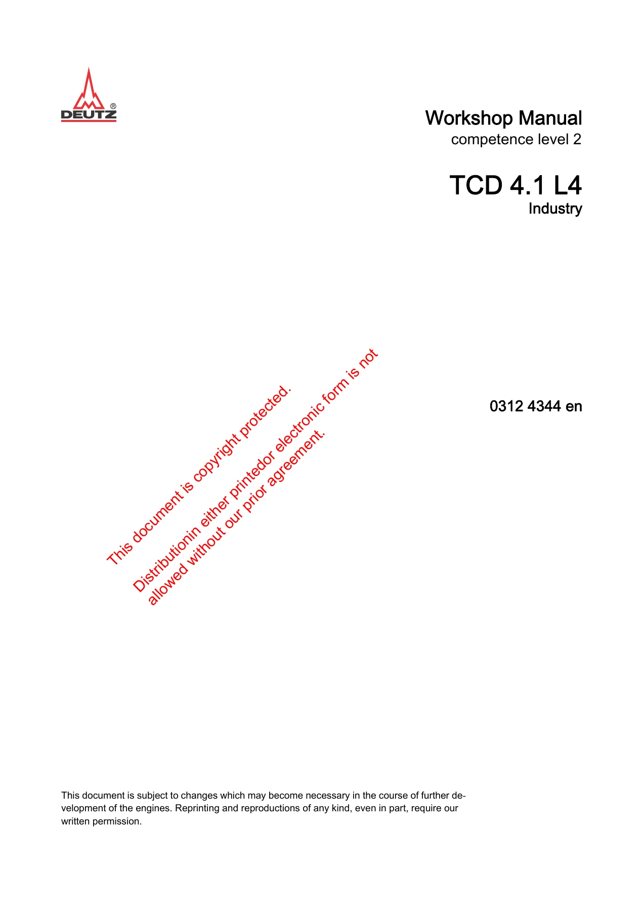
Deutz TCD 4.1 L4 Workshop Manual 0312 4344 PDF Download

Original price was: $39.95.Current price is: $24.95.

Complete DEUTZ TCD 4.1 L4 engine workshop manual (order no. 0312 4344 en, 2nd edition, 06/2014). 510 pages of job cards, tightening specs, technical data and special tool references for the four-cylinder TCD 4.1 L4 diesel engine. Instant PDF download.

⚑
Instant PDF Download
Available immediately
πŸ’Ύ
Save to Your Device
Download & keep forever
πŸ›‘οΈ
Antivirus Scanned
100% virus-free
🌍
Trusted Worldwide
175,000+ customers

Description

Deutz TCD 4.1 L4 Workshop Manual – Order No. 0312 4344 en

This is the complete workshop manual for the DEUTZ TCD 4.1 L4 diesel engine, published by DEUTZ AG under order number 0312 4344 en. The 2nd edition, dated 06/2014, runs to 510 pages of job cards, tightening specifications, technical data tables and special tool references covering the TCD 4.1 L4 four-cylinder engine and the systems installed on it. Every repair procedure in this Deutz TCD 4.1 L4 workshop manual is written as a numbered job card with step-by-step instructions, exploded illustrations, torque values and required tooling.

File Details

  • Manual type: Workshop Manual (job cards + technical data)
  • Brand / Publisher: DEUTZ AG
  • Engine: TCD 4.1 L4
  • Order number: 0312 4344 en
  • Edition / Date: 2nd edition, 06/2014
  • Language: English
  • Page count: 510 pages
  • File format: PDF
  • Contents: Foreword, General, Safety instructions / User information, Job card overview (alphabetical and numerical), Job cards, Special tools

Chapters Covered

  • Foreword and general information
  • Safety instructions / user information (including common rail and exhaust aftertreatment warnings)
  • Job card overview – sorted alphabetically
  • Job card overview – sorted numerically
  • Job cards – crankcase breather, crankshaft sealing ring, shaft sleeve, front cover
  • Job cards – lubricating oil pan, V-rib belt pulley, flywheel
  • Job cards – compression pressure check, cylinder head cover, valve clearance
  • Job cards – lubricating oil cooler and oil cooler housing
  • Job cards – control block, high-pressure pump, injector (1600 bar injection system)
  • Job cards – fuel supply pump, fuel filter, fuel pre-filter, fuel lines
  • Job cards – charge air line, charge air manifold
  • Job cards – coolant pump, thermostat, thermostat housing, coolant pipes
  • Job cards – belt tensioner, fan drive
  • Job cards – exhaust line, exhaust gas recirculation (flutter valve, cooler, actuator, AGS sensor)
  • Job cards – exhaust gas turbocharger, lubricating oil lines to/from turbocharger
  • Job cards – generator, starter
  • Job cards – impulse transmitters (crankshaft / camshaft), pressure and temperature sensors
  • Job cards – ignition cable, ignition device, spark plug, control unit (spark plugs)
  • Job cards – connection housing, engine mounting, turning gear
  • Job cards – heating flange, mixing pipe, throttle valve, charge air manifold (start aid)
  • Job cards – diesel particle filter (System 8.5″ axial and radial)
  • Job cards – burner, air compressor, air mass flow sensor, pressure transmitter
  • Job cards – coolant compressor, hydraulic pump, hydraulic pump drive
  • Special tools – complete illustrated tool listing with order numbers

What This Deutz TCD 4.1 L4 Workshop Manual Gives You

DEUTZ job cards are organised by module number (for example W 01-01-01 for the crankcase breather, W 19-01-01 for the injector, W 71-05-01 for the diesel particle filter). Each card opens with the parts shown in an exploded view, lists the standard and special tools required, and then walks through removal and installation step by step with tightening torques called out at the point of use. At the end of each card a Tightening specifications table repeats the critical values – so there is no need to cross-reference between chapters for a torque figure.

The 510-page Deutz TCD 4.1 L4 repair manual covers the full engine mechanically and electrically: cylinder head, valve clearance setting with rotation angle disc, injector replacement on the 1600 bar common rail system, high-pressure pump removal and installation, rail, pressure limiting valve, fuel lines, charge air circuit, cooling system, exhaust gas recirculation, turbocharger, and the full exhaust aftertreatment chain (burner, diesel particle filter, ignition device, spark plug). Component groups such as the hydraulic pump drive, generator, starter and connection housing are covered in their own job cards.

Safety content is included throughout, because the TCD 4.1 L4 uses a common rail fuel system with operating pressures up to approximately 2000 bar, and the burner ignition system operates at up to 10000 volts. The manual documents the required waiting time after engine shutdown before opening the fuel system, the cleanliness measures for high-precision common rail components, and the handling precautions for AdBlue and DPF service work. Anyone performing Deutz TCD 4.1 L4 maintenance or repair should read these sections before starting.

Technical Data in This Manual

Testing and setting data appears at the end of the relevant job card – for example the valve clearance values for inlet and exhaust valves, the thermostat opening temperature and stroke, and the injector clamping claw tightening sequence. Tightening specifications tables list each fastener by ID number, screw type and torque value, with a stated tolerance of +/- 10% for torque wrench application. The special tools chapter reproduces every required DEUTZ tool with its order number and a photograph, so you can identify what is needed before starting a job.

Who This Manual Is For

Owners, operators and independent workshops servicing the DEUTZ TCD 4.1 L4 will find the workshop manual written for the technician, not the driver. It assumes access to a workshop, the listed special tools and the ability to follow safety-critical procedures. For routine maintenance and care instructions outside the scope of major repair, DEUTZ refers to the separate operation manual – this document is the job card / workshop level manual, and it is the one that gives you the torque values, the assembly sequences and the tool numbers.

Complete PDF Bookmark Tree

Complete Bookmarks

The complete bookmarks in the β€œDeutz TCD 4.1 L4 Workshop Manual 0312 4344 PDF Download” are as follows:

Workshop Manualp. 1
Table of contentsp. 3
1 Forewordp. 5
2 Generalp. 9
3 Safety information / User informationp. 13
5 Job card overviewp. 21
5.1 Sorted alphabeticallyp. 21
5.2 Sorted numericallyp. 29
6 Job cardsp. 37
Removing and installing the crankcase bleedingp. 39
Renewing the crankshaft sealing ringp. 45
Assembling/disassembling shaft sleeve on the crankshaftp. 51
Removing and installing the front cover (Fastening parts)p. 55
Closing partsp. 61
Holderp. 63
Oil filler neckp. 65
Oil filler neckp. 67
Linep. 69
Guide tubep. 71
Removing and installing the lubricating oil pan (metal sheet lubricating oil pan)p. 73
Removing and installing the V-rib belt pulleyp. 81
Removing and installing the flywheel (Fastening parts)p. 85
Add-on partsp. 89
Checking the compression pressurep. 91
Removing and installing the cylinder head coverp. 95
Transport eyep. 99
Engine suspensionp. 101
Renewing the crankshaft sealing ring (flywheel side)p. 103
Checking and setting the valve clearancep. 107
Removing and installing the lubricating oil coolerp. 113
Removing and installing the lubricating oil cooler housing (Fastening parts)p. 117
Closing partsp. 121
Fastening partsp. 123
Installing the lubricating oil filterp. 125
Removing and installing the control block (Fastening parts)p. 127
Removing and installing the high-pressure pump (Fastening parts)p. 131
Removing and installing the injector (1600bar Injection system)p. 137
Removing and installing the fuel supply pump (Fastening parts)p. 149
Connection partp. 153
Fuel pre-filterp. 155
Fuel filterp. 157
Removing and installing the fuel line (control block – high-pressure pump)p. 159
Removing and installing the railp. 163
Removing and installing the fuel line (Rail, cylinder head, control block)p. 173
Fuel linep. 179
Fuel linep. 181
Removing and install the charge air linep. 183
Fastening partsp. 187
Connection linep. 189
Charge air manifoldp. 191
Adapterp. 193
Lubricating oil linep. 195
Coolant linep. 197
Coverp. 199
Removing and installing the coolant pumpp. 201
Drive componentsp. 205
Removing and installing the thermostatp. 207
Checking the thermostat (in the removed state)p. 213
Removing and installing the thermostat housingp. 217
Removing and installing the pipe (cylinder head – exhaust gas recirculation)p. 223
Closing partsp. 227
Line (cylinder head – exhaust gas recirculation)p. 229
Line (cylinder head – exhaust gas recirculation)p. 231
Removing and installing the belt tensioner (V-rib belt, level 1)p. 233
Fastening partsp. 237
Removing and installing the exhaust line (add-on parts)p. 239
Removing and installing the flutter valvep. 243
Removing and installing the coolerp. 249
Removing and installing the actuatorp. 263
Removing and installing the sensor (AGS sensor) (exhaust gas mass flow)p. 269
Shielding platep. 273
Holder (Cylinder head, exhaust gas circulation, coolant line)p. 275
Mountingp. 277
Pressure sensor (Exhaust gas backpressure)p. 279
Line (Burner, pressure sensor for exhaust gas backpressure)p. 281
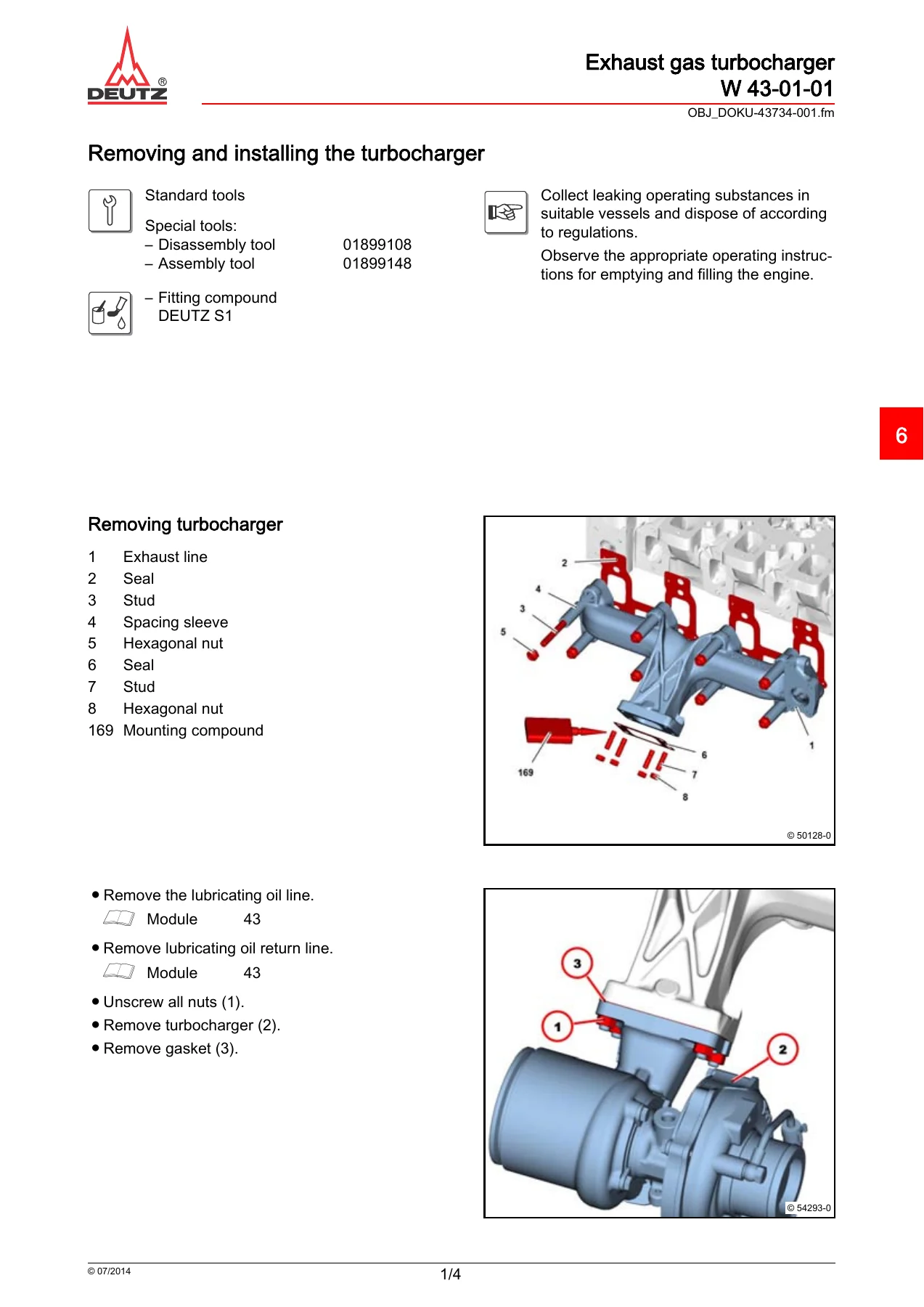
Removing and installing the turbochargerp. 283
Removing and installing the lubricating oil line (exhaust turbocharger)p. 287
Removing and installing the lubricating oil return line (exhaust turbocharger)p. 291
Removing and installing the generator (V-rib belt, level 1)p. 295
Removing and installing the starter (Fastening parts)p. 299
Shielding platep. 303
Generatorp. 305
Generator Drive componentsp. 307
Fastening partsp. 309
Removing and installing the impulse transmitter (crankshaft) (Fastening parts)p. 311
Removing and installing the impulse transmitter (camshaft) (add-on parts)p. 315
Removing and installing the pressure/temperature sensor (charge air)p. 319
Removing and installing the ignition cable (Control unit – burner)p. 323
Closing partsp. 327
Holder (Relay)p. 329
Holding platep. 331
Temperature sensorp. 333
Installing and removing turning gearp. 335
Installing and removing turning gear (Torsional vibration damper)p. 339
Mounting engine on assembly block and demountingp. 341
Removing and installing the connection housingp. 347
Connection housingp. 353
Removing and install the heating flangep. 355
Disassembling and assembling the heating flangep. 359
Removing and installing charge air manifoldp. 363
Removing and installing the mixing pipep. 367
Removing and installing the throttle valvep. 371
Connection nozzlep. 375
Solenoid valve (Flush air line)p. 377
Removing, installing and checking the spark plugp. 381
Remove and install control unit (spark plugs)p. 385
Removing and installing the ignition devicep. 389
Removing and installing temperature transmitter (burner)p. 395
Removing and installing the air compressorp. 399
Removing and installing the sensor (Air mass flow rate)p. 403
Removing and installing the pressure transmitter (Air compressor)p. 407
Dismantling and assembling the diesel particle filter (System 8.5" axial and radial – removed)p. 411
Heat protection platep. 423
Shielding platep. 425
Holder (Gearcase, air line)p. 427
Holderp. 429
Holderp. 431
Holderp. 433
Retainer platep. 435
Retainer platep. 437
Transport eyep. 439
Compensator structurep. 441
Air line (air compressor – burner)p. 443
Pipesp. 445
Pipesp. 447
Line (Burner, pressure sensor for exhaust gas backpressure)p. 449
Holder (Exhaust counter pressure sensor)p. 451
Solenoid valve (Flush air line)p. 453
Connection line (burner)p. 455
Support (burner)p. 457
Burnerp. 459
Add-on partsp. 463
Add-on partsp. 465
Removing and installing the hydraulic pumpp. 467
Removing and installing hydraulic pump drivep. 471
Dismantling and assembling the hydraulic pump drivep. 475
Closing partsp. 481
Hydraulic pump drivep. 483
Hydraulic pump drivep. 485
Closing partsp. 487
Connection nozzlep. 489
Shielding platep. 491
8 Special toolsp. 493


IMAGES PREVIEW

Deutz TCD 4.1 L4 Workshop Manual 0312 4344 PDF Download β€” PDF page 1 preview
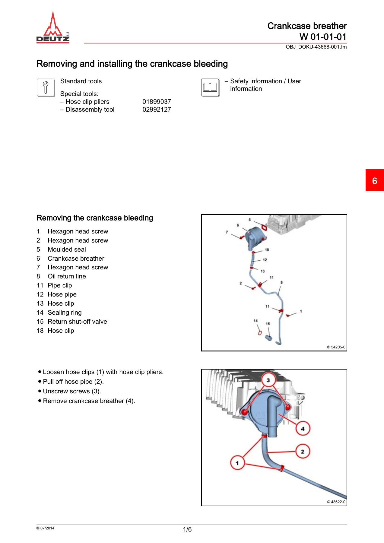
Deutz TCD 4.1 L4 Workshop Manual 0312 4344 PDF Download β€” PDF page 39 preview
Deutz TCD 4.1 L4 Workshop Manual 0312 4344 PDF Download β€” PDF page 283 preview

Instant PDF Delivery

This Deutz TCD 4.1 L4 workshop manual is delivered as a PDF download immediately after purchase – no shipping, no waiting for a disc. Read it on a laptop, tablet or phone in the workshop, and print whichever job card you need for the task at hand. Having the correct procedures and specs on hand means the TCD 4.1 L4 can be repaired and maintained the way DEUTZ intended, with the right torques, the right sequence and the right tooling.
Reviews

There are no reviews yet.

Be the first to review “Deutz TCD 4.1 L4 Workshop Manual 0312 4344 PDF Download”

What Our Customers Say

β˜…β˜…β˜…β˜…β˜… Live reviews from customers
Loading customer reviews...
0
    0
    Your Cart
    Your cart is emptyReturn to Shop
    πŸ›’
    Recently Purchased
    πŸ•’ verified order