

Drager Narkomed 3 Anesthesia System Technical Service Manual – PDF
Original price was: $39.95.$23.95Current price is: $23.95.
Complete Drager Narkomed 3 (NM3) Anesthesia System Technical Service Manual, Part S002013 Rev. V. Covers diagnostics, error codes, troubleshooting flow charts, 37 field replacement procedures, calibration, PMS testing, firmware updates and spare parts listings.
Description
Drager Narkomed 3 Anesthesia System Technical Service Manual
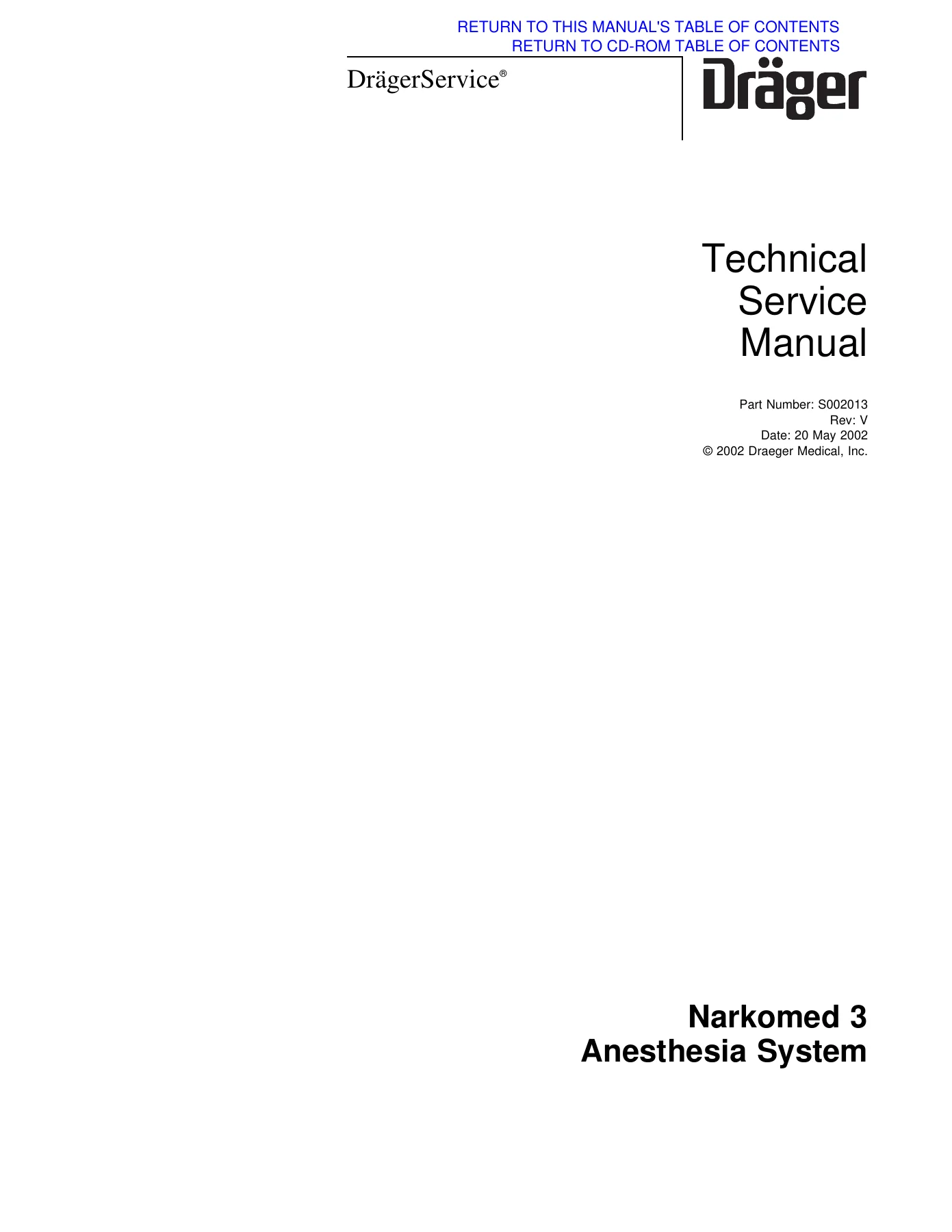
This Drager Narkomed 3 Anesthesia System Technical Service Manual is the full technical service document for the Narkomed 3 (NM3) anesthesia machine, issued by Draeger Medical, Inc. under part number S002013, Revision V, dated 20 May 2002. Running roughly 324 pages, it walks a qualified Technical Service Representative through on-board diagnostics, fault isolation, field-replaceable assembly procedures, calibration and adjustment, periodic manufacturer’s service testing, firmware replacement and the illustrated spare parts listings that keep these machines running in the operating room.
Few anesthesia workstations reward guesswork less than the Narkomed 3. Gas delivery, oxygen ratio control, ventilator bellows, breathing pressure monitoring and the analyzer chain all interact, and the manual treats them as one system rather than a stack of unrelated boxes. Every procedure opens with the same discipline: drain pressure, isolate the circuit, remove the table top or rear cover, disconnect at the marked fittings, and verify with a leak test or a specified pressure reading before the machine goes back into service. That structure is what makes this Narkomed 3 service manual usable in the field rather than just readable.
File Details
- Manual type: Technical Service Manual
- Brand / publisher: Draeger Medical, Inc. (DragerService)
- Model covered: Narkomed 3 Anesthesia System (NM3)
- Part number: S002013
- Revision: Rev. V
- Publication date: 20 May 2002
- Language: English
- Page count: Approximately 324 pages
- File format: PDF
Chapters Covered
- Section 1 — Introduction: service recommendations, how to use the manual, general troubleshooting guidelines, warnings and cautions conventions
- Section 2 — Diagnostics: Service Selection Screen, Configuration Screen, Service Data Screen, and the Narkomed 3 error code table (E00 ROM error through E10 ADC reference out of range)
- Section 3 — Troubleshooting: power supply and voltage distribution, distribution block voltages, Multispec analyzer power supply voltages, and troubleshooting guide flow charts for blank or incorrect CRT display, O2MED, BAROMED, SaO2, SPIROMED and SPHYGMOMED monitors, Multispec monitor and analyzer errors, serial interface communication failure, and loss of keypad response
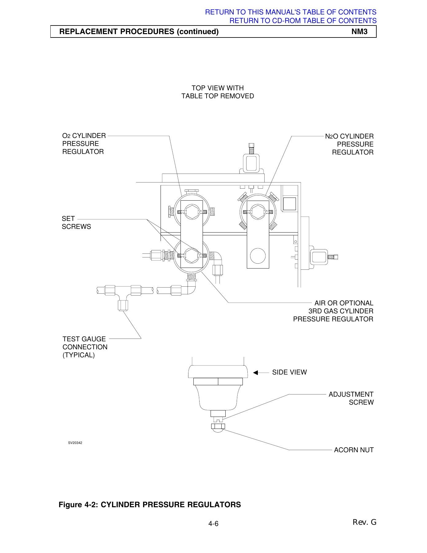
- Section 4 — Replacement Procedures: cylinder yoke assemblies, cylinder pressure regulators, cylinder cutoff valves (Canada), cylinder and pipeline pressure gauges, flowmeters, flow control valves, oxygen supply pressure failure protection device, oxygen supply pressure alarm switch, oxygen supply pressure alarm whistle (Canada), oxygen ratio monitor/controller, vaporizers, O2 flush valve, ventilator controller assembly, ventilator solenoid valve, convenience outlet AC power filter, inspiratory flow regulator, ventilator bellows valve and guide assembly, alarm channel, Multispec analyzer, ECC (serial interface) module, Sphygmomed module, monitors, trend assembly, CCC (Central Communications Controller) assembly, CRT assemblies, keypads, pulse oximeter module, power controller assembly, Multispec power supply, primary power supply, battery pack, caster, Spiromed respiratory volume sensor, oxygen sensor, manual sphygmomanometer, auxiliary oxygen flowmeter, PEEP valve magnet assembly
- Section 5 — Adjustment and Calibration Procedures: cylinder pressure regulator adjustment (including CO2), oxygen supply pressure alarm switch adjustment, oxygen ratio monitor/controller adjustment, oxygen monitor calibration (offset and ambient air), Baromed monitor calibration, Multispec analyzer calibration and flowrate adjustment, Multispec 4610 analyzer calibration and flowrate adjustment, CRT alignment, vaporizer interlock adjustment, vaporizer select switch adjustment, Capnomed (B) barometric pressure adjustment for high altitudes, Capnomed span calibration
- Section 6 — PMS Procedure: manual sphygmomanometer, yoke assemblies and gauges, high pressure leak tests for each gas, oxygen supply pressure alarm, oxygen supply failure protection, O2 Med offset calibration, O2 Med accuracy and alarm tests, oxygen concentration tests, flowmeter tests, freshgas leak test, MAN/AUTO selector valve repack, absorber system inspection, Spiromed sensor lubrication, breathing system leak test, absorber flow direction and leak test, APL valve test, PEEP bypass valve, ventilator test, ventilator relief valve test, bellows drive gas leak test, bellows PEEP valve test, pressure limit control test, trace and trend functions, Spiromed monitor, alarm circuit delay test, Baromed monitor calibration, continuing/high/sub-atmospheric pressure alarms, oxygen ratio monitor control test, scavenger interface, A/C scavenger, open reservoir scavenger, Sphygmomed, Nellcor and Novametrix O2 SatMed, Capnomed CO2 monitor, vapor exclusion system and indicator lamps, Multispec accuracy test, accessory and visual inspection, battery circuit test, ground continuity test, chassis leakage current test, service data, oxygen flush test, operator’s manual and final check
- Section 7 — Software Update Procedure: monitors firmware replacement, CCC assembly firmware replacement, trend assembly firmware replacement, ECC (serial interface) module firmware replacement, CRT assembly firmware replacement, gas analyzer interface PCB (4610) firmware replacement
- Section 8 — Spare and Replacement Parts: illustrated part listings for monitor chassis, monitors, CCC, trend/MUX and CRT assemblies, front bezel and serial interface, Multispec analyzer and PCB assemblies, Sphygmomed and pulse oximeter modules, ventilator box, bellows valve and guide assembly, pipeline inlets, failsafe devices, alarm channel, ORMC and vaporizer select switches, flow tubes, gauges, flow control valves, yokes, regulators, flush valves, interface panels, power supplies, casters, absorber assembly, MAN/AUTO selector valves, auxiliary O2 flowmeter and the full scavenger range
Read end to end, this Drager Narkomed 3 technical service manual gives a technician the complete service logic for the machine: how each subsystem is powered, how the monitors report faults, which assemblies are considered field-replaceable, what each replacement has to be verified against afterwards, and what the numbers should be when the verification is done. The diagnostics section alone changes how a fault gets approached — instead of swapping parts, the flow charts key a symptom to a specific assembly and a specific procedure number.
Diagnostics and Error Codes
The Narkomed 3 reports its internal state directly. On power-up each monitor runs a six-second self-diagnostic and lamp test, and the display window shows a power-up code. The manual lists the codes and what they mean: E00 ROM error, E01 RAM error, E02 ADC did not start conversion, E03 ADC conversion too long, E04 ADC reading out of range, E05 CTC error, E06 calibration error, E07 communication lost, E08 shorted switch, E09 non-functional pneumatic control element, and E10 ADC reference out of range. Behind those codes sit the service screens — the Service Selection Screen, Configuration Screen and Service Data Screen — reached through a hidden key combination and used to set power-up defaults, read total machine hours, reset the service date, and confirm the firmware version loaded in each subassembly. That last function matters every time a firmware chip is replaced, because the Service Data Screen is how the new version gets verified.
Replacement and Calibration Work
The replacement section is the working core of the book. Thirty-seven procedures cover everything from a cylinder yoke filter and check valve up through the oxygen ratio monitor/controller, the ventilator bellows valve and guide assembly, the power controller, the primary power supply and the battery pack. Each one is written with the safety sequence intact — bleed the circuit, disconnect pipeline hoses, set the System Power switch to STANDBY, remove the table top or rear cover as needed — and each one closes by pointing back at the PMS procedure so nothing goes back into service untested.
Calibration follows the same pattern. Oxygen monitor offset and ambient air calibration, Baromed zero and span adjustment against a digital pressure meter, Multispec flowrate and span calibration with a certified sample gas, Capnomed span calibration, CRT alignment against defined picture height and width, vaporizer interlock and select switch adjustment, and cylinder regulator output settings tabulated against cylinder pressure so the regulator is compensated correctly across its working range.
The PMS Procedure and Certification Program
Section 6 is a complete periodic manufacturer’s service routine, not a checklist of suggestions. It includes high pressure leak tests for each gas with a stated maximum loss, oxygen supply failure protection tests, oxygen concentration tests across every gas combination the machine supports, breathing system and freshgas leak tests, ventilator timing and tidal volume verification, pressure alarm threshold testing, scavenger negative and positive pressure relief tests, electrical safety testing including ground continuity and chassis leakage current, and the vapor concentration verification that determines whether a vaporizer stays on the machine. The accompanying certification instructions explain the A/B/C/D certification levels and the conditions that can make a machine uncertifiable.
Why This Manual Matters
An anesthesia machine is not a piece of equipment where a plausible guess is good enough. Oxygen concentration, breathing pressure, tidal volume and agent concentration all have defined acceptable ranges, and this Narkomed 3 anesthesia service manual supplies the ranges, the test setups and the adjustment points needed to prove a machine is inside them. The leak test limits, the regulator output tables, the alarm activation windows and the flow rate tolerances are all stated as numbers, so a service visit ends with a documented result rather than an opinion.
Whether you are chasing an E07 communication fault, replacing a bellows valve assembly, recalibrating a Multispec analyzer, verifying a vaporizer’s output or running a full periodic certification, the procedure is here with the fittings marked, the torque values given and the acceptance criteria spelled out.
IMAGES PREVIEW
Instant PDF Delivery
The manual is delivered as an instant PDF download — no shipping, no waiting, no physical binder to track down. Open it on a laptop in the shop, a tablet at the machine, or a phone in the OR corridor, and print whichever procedure you need for the job in front of you. Search the document for a part number, an error code or a procedure reference and go straight to the page. For anyone maintaining a Narkomed 3, this is the reference that turns a difficult service call into a defined sequence of steps.
Reviews
There are no reviews yet.