★ TRUSTED BY 321,897+ PROFESSIONALS WORLDWIDE
🏒
Trusted Business
Verified & Licensed
πŸ›‘οΈ
Virus Free Files
100% Safe Downloads
πŸ”’
Secure Payment
SSL Protected
⚑
Instant Delivery
Available Immediately
Sale!

elisa 600 / elisa 800 Technical Service Manual – SW 2.01.x and Later PDF

Original price was: $39.95.Current price is: $22.95.

216-page English technical service manual for the LΓΆwenstein Medical elisa 600 and elisa 800 intensive care ventilators running software SW 2.01.x and later. Covers calibration, maintenance, troubleshooting, alarm codes, component replacement, software updates and Philips/Salvia serial data integration.

⚑
Instant PDF Download
Available immediately
πŸ’Ύ
Save to Your Device
Download & keep forever
πŸ›‘οΈ
Antivirus Scanned
100% virus-free
🌍
Trusted Worldwide
175,000+ customers

Description

elisa 600 / elisa 800 Technical Service Manual – SW 2.01.x and Later

This elisa 600 / elisa 800 Technical Service Manual is the full workshop-level reference for servicing the LΓΆwenstein Medical (Salvia) intensive care ventilators on software revision SW 2.01.x and later. Running 216 pages, it walks through the entire service lifecycle of these machines – power-up testing, system testing, calibration of every flow and pressure sensor, alarm troubleshooting, preventive maintenance schedules, board-level component replacement, software updates and serial data integration with Philips monitors and PDMS systems. It is the document a technician opens before touching an elisa 600 or elisa 800 ventilator.

File Details

  • Manual type: Technical Manual (service, repair, calibration, maintenance)
  • Brand / manufacturer: LΓΆwenstein Medical SE & Co. KG (Salvia)
  • Models covered: elisa 600, elisa 800
  • Software version: SW 2.01.x and later (document describes up to SW 2.08.x)
  • Language: English
  • Page count: 216 pages
  • File format: PDF
  • Revision: Rev. 02, dated 2021-05-06

Chapters Covered

  • Introduction – About this Technical Manual, instructions for use, standard service work
  • Differences between elisa 600 and elisa 800 – hardware and software comparison (VIT, flow capacity, valve type, nebulizer interface, Paux ports, patient categories)
  • General information – Main hardware components (ventilator unit, control unit, valve bar, battery, cart), symbols used on the device and packaging, abbreviations, technical data, electrical and gas supply specifications, safety features, increments and maximum performance range, default parameters, adjustment ranges, default alarm limits
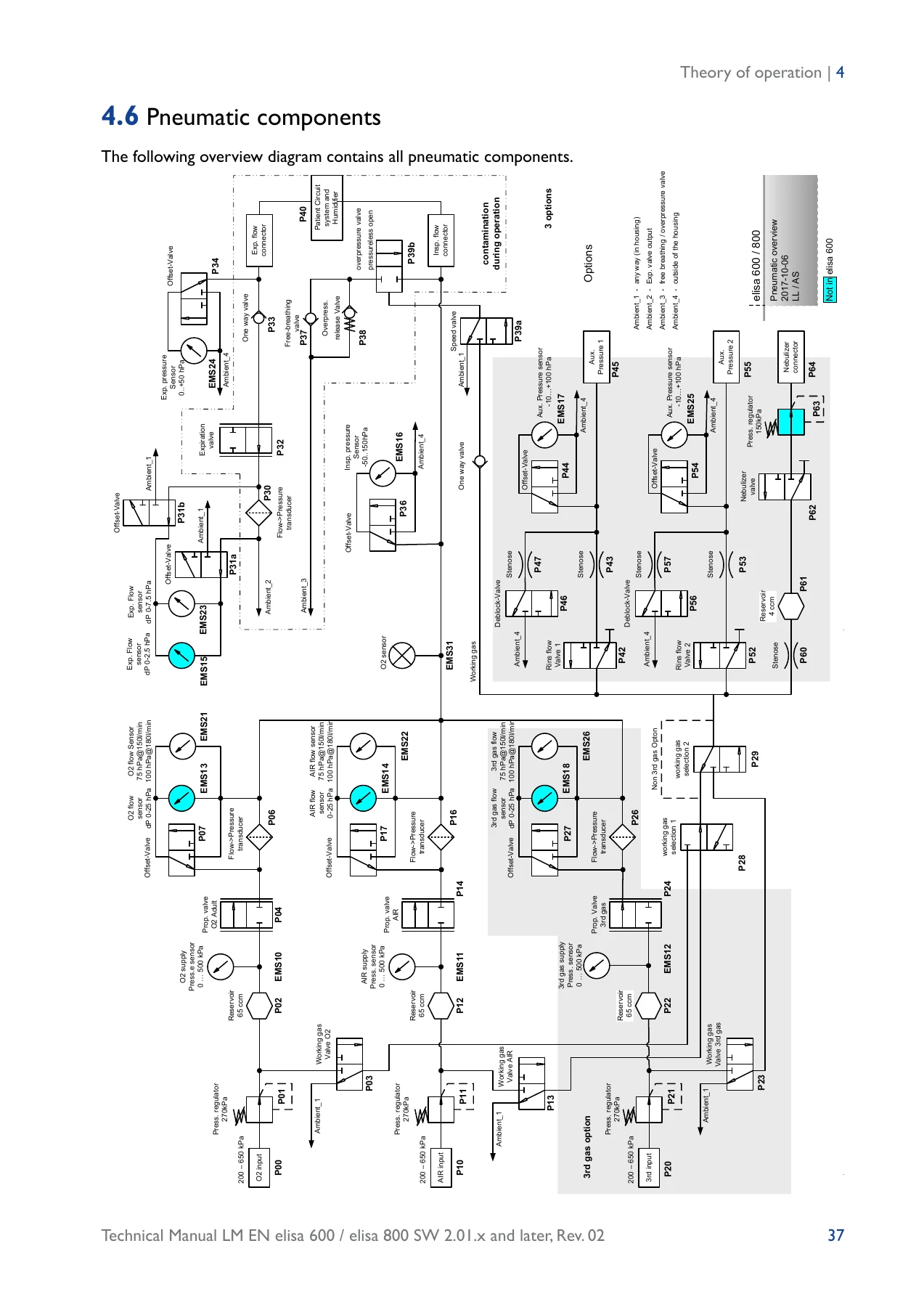
  • Theory of Operation – General and functional description, function chart of the elisa 600 / 800 ventilator, safety features, localising the operator menus, pneumatic components (with explanatory tables), electrical components (main engine power management, sensors, valves/actuators, control unit)
  • Initial Commissioning – Initial operation, accessories, complete first-time commissioning checklist
  • Service Mode: Tests and Calibrations – Power-up test, system test (patient category selection, test performance), operational tests, test lung, configuration, service mode (power manager, main controller, control unit, touchscreen controller, system information, pneumatic, restricted area), offset calibration, O2 sensor calibration, inspiratory O2 flow calibration and check, inspiratory AIR flow calibration and check, expiratory flow calibration and check, expiration pressure calibration and check, nebulizer pressure and flow checks, Paux I and Paux II functional tests, safety tests after service work
  • Troubleshooting – Problems, causes and corrective measures table, troubleshooting instructions, alarm system, alarm verification for blocked and partially blocked breathing circuits, alarm priorities, full alarm message reference with error codes and corrective measures, error messages during power-up test, error messages during system test, fault analysis of faulty pneumatic components
  • Maintenance – General instructions, cleaning and disinfecting, disposal (battery, packaging), maintenance schedule, annual maintenance, 6-year maintenance (control unit removal, housing opening, O2 pressure regulator replacement, lithium button cell replacement, monitor refitting)
  • Replacing components – Inserting or replacing the battery, replacing the main board (pneumatic assembly removal, cable disconnection, board replacement, reinstallation), replacing the nebulizer pressure regulator, replacing the power unit board, exchanging the Paux ports (legacy and new versions)
  • Software update – General information, updating the software (preparations, saving new software, installing, verifying), device configuration, download error troubleshooting
  • Hardware update – Adding interface boards (CO2, mesh nebulizer, PDMS, nurse call, BF cards), replacing interface boards, installation of new BF interface boards
  • Serial data transfer – Salvia protocol, Philips protocol with Salvia protocol (transmitted information), Philips protocol with Philips monitor / PDMS system (device components, installation overview, troubleshooting, displayed information, adjustable settings)
  • Installation with support arm – Insulation measurement procedure and test report
  • Order numbers – Service accessories and specifications, test lung kit, tool kit, maintenance kits, rechargeable batteries, valve bar parts, gas connection filter, pressure regulator, fan filter foam mat, button cell battery, interface boards

Across these chapters the elisa 600 / elisa 800 Technical Service Manual supplies the pneumatic and electrical schematics, component identification tables, sensor tolerance windows, calibration step sequences, alarm cause-and-effect tables, torque and part numbers, and step-by-step disassembly and reassembly procedures required to keep both ventilators running to specification. It documents both the older rear-panel layout (through SW revision 2.06) and the revised layout introduced with SW 2.07, including the BF interface card configuration.

What This Manual Supports

With this elisa 600 / elisa 800 service manual on hand, a technician can safely complete every procedure the ventilators require across their service life – running the power-up test, carrying out the full system test with a test lung, calibrating every flow and pressure sensor in the pneumatic circuit, verifying alarm signalling devices, diagnosing an error code down to the correct corrective action, replacing the main board, power unit board, nebulizer pressure regulator or Paux ports, performing annual and 6-year preventive maintenance, updating the software via USB, and configuring the serial data link to a Philips IntelliVue monitor through the PDMS system. The document keeps the specific tolerances and part references that matter – flow correction factors between 0.8 and 1.2, expiration pressure targets, nebulizer flow and pressure values, cuff pressure ranges, Paux triggering times, valve part numbers – all in one place.

Correct calibration data and procedure sequences are what keep a ventilator’s tidal volume, pressure delivery and O2 concentration trustworthy at the bedside. Guessing, or using a generic ICU ventilator guide, risks drifting flow values, mis-triggered alarms and, worse, undetected pneumatic faults. This manual gives the exact reference points for the elisa 600 and elisa 800 instead.

Complete PDF Bookmark Tree

Complete Bookmarks

The complete bookmarks in the β€œelisa 600 / elisa 800 Technical Service Manual – SW 2.01.x and Later PDF” are as follows:

1.1 About this Technical Manualp. 8
1.1.1 Instructions for usep. 8
1.1.2 Standard service workp. 8
2.1 Differences between elisa 600 and elisa 800p. 10
DO-628263p. 213
3.1. Main hardware componentsp. 12
3.1.2 Control unitp. 16
3.1.3 Valve barp. 16
3.1.4 Batteryp. 17
3.1.5 Cart (optional)p. 17
3.2 Symbols used on the devicep. 17
3.3Additional symbols used on the packagingp. 18
3.4 Abbreviations used in the instructions for use and on the devicep. 19
3.5 Technical datap. 23
3.5.1 Supplyp. 25
3.5.2 Safety featuresp. 26
3.5.3 Control unitp. 26
3.6 Increments and maximum performance rangep. 27
3.7 Default parametersp. 30
3.7.1 Default parametersp. 30
3.6.2 Adjustment rangesp. 31
3.6.3 Default alarm limitsp. 31
4.1 General descriptionp. 34
4.2 Functional descriptionp. 34
4.3 Function chart of the elisa 600 / 800 ventilatorp. 35
4.4 Functions of the elisa 600 / elisa 800 ventilatorsp. 36
4.4.1 Safety featuresp. 36
4.5 Localising the operator menusp. 36
4.6 Pneumatic componentsp. 37
4.7 Electrical componentsp. 41
5.1 Initial operationp. 56
5.1.1 Accessoriesp. 56
5.1.2 Checklist for the initial commissioning of the devicep. 56
6.1 Power-up-testp. 60
6.2 System testp. 61
6.2.1 Select patient categoryp. 61
6.2.2 Performing the system testp. 61
6.3 Operational testsp. 62
6.4 Testing a test lungp. 62
6.5 Configurationp. 63
6.6 Service Modep. 63
6.6.1 Calibration functions (see section β€œ6.7 Calibrations”)p. 64
6.6.2 Power managerp. 64
6.6.3 Main controllerp. 65
6.6.4 Control unitp. 65
6.6.5 Touchscreen controllerp. 66
6.6.6 System informationp. 66
6.6.7 Pneumaticp. 67
6.6.8 Restricted areap. 67
6.7 Calibrationsp. 67
6.7.1 General Informationp. 67
6.7.2 Offset calibrationp. 69
6.7.3 Calibrating the O2 sensorp. 69
6.7.4 Calibrating the inspiratory O2 flowp. 70
6.7.5 Checking the inspiratory O2 flowp. 71
6.7.6 Calibrating the inspiratory AIR flowp. 72
6.7.7 Calibrating the inspiratory AIR flowp. 73
6.7.8 Calibrating the expiratory flowp. 74
6.7.9 Checking the expiratory flow with AIRp. 75
6.7.10 Calibrating the expiration pressurep. 75
6.7.11 Checking the expiration pressurep. 76
6.7.12 Checking the nebulizer pressure (only elisa 800)p. 77
6.7.13 Checking the nebulizer flowp. 78
6.7.14 Functional test for Paux I and Paux IIp. 78
6.8 Safety tests after service workp. 81
6.8.1 Testing the BF cardsp. 81
7.1 Problems – Causes – Corrective measuresp. 84
7.2 Troubleshooting instructionsp. 84
7.3 Alarm systemp. 85
7.3.1 Test of the signalling devicesp. 85
7.3.2 Alarm verification in the presence of a blocked breathing circuitp. 85
7.3.3 Alarm verification in the presence of a partially blocked breathing circuitp. 85
7.4 Alarm prioritiesp. 85
7.5 Alarm messages during operationp. 86
7.6 Error messages during the power-up testp. 110
7.7 Error messages during system testp. 112
8.1 General instructionsp. 118
8.2 Cleaning and disinfecting the devicep. 118
8.3 Disposal of elisa 600 / elisa 800p. 118
8.3.1 Batteryp. 119
8.2.3 Packagingp. 119
8.4 Maintenance schedulep. 119
8.5 Annual Maintenancep. 120
8.5.1 Examine the device for visible damage.p. 120
8.5.2 Replace all silicone components of the valve barp. 120
8.5.3 Replace the fan filter matp. 123
8.5.4 Replace the O-rings and sintered filter of both NIST screw joints.p. 124
8.6 6-Year Maintenancep. 125
8.6.1 Removing the control unitp. 125
8.6.2 Opening the housingp. 126
8.6.3 Replacing the O2 pressure regulatorp. 127
8.6.4 Replacing lithium button cell battery (3V CR 2032)p. 128
8.6.5 Closing the housing againp. 128
8.6.6 Fixing the monitorp. 129
9.1 Inserting or replacing the batteryp. 132
9.2 Replacing the main boardp. 133
9.2.1 Removing the pneumatic assemblyp. 133
9.2.1.1 Preparationsp. 133
9.2.1.2 Disconnect the cable jointsp. 134
9.2.1.3 Unscrew the device feetp. 135
9.2.1.4 Remove the screwsp. 135
9.2.1.5 Removing the pneumatic assemblyp. 136
9.2.2 Remove connections from the main boardp. 136
9.2.3 Inserting a new main boardp. 138
9.2.4 Reinstall the pneumatic assembly (installation in reverse order of removal)p. 139
9.3 Replacing the pressure regulator for nebulizerp. 140
9.4 Replacing the power unit boardp. 142
9.5 Exchanging the Paux portsp. 143
9.5.1 Removing the legacy Paux portsp. 143
9.5.2 Mounting the new Paux portsp. 144
10.1 General informationp. 146
10.2 Updating the softwarep. 146
10.2.1 Preparationsp. 147
10.2.2 Saving new software in the devicep. 147
10.2.3 Installing the new softwarep. 150
10.2.4 Verifying the softwarep. 152
10.3 Troubleshootingp. 153
10.3.1 Download errorsp. 153
11.1 General Informationp. 156
11.2 Installation of additional interface boards (not new BF cards)p. 156
11.3 Preparationsp. 157
11.4 Adding CO2 interface board to elisa 600p. 158
11.5 Add Mesh nebulizer interface card to the elisa 600p. 160
11.6 Adding PDMS interface board to elisa 600p. 162
11.7 Fitting elisa 600 / elisa 800 with Philips PDMS interface boardp. 163
11.8 Replacing interface boards in elisa 600 or elisa 800p. 165
11.9 Adding the nurse call interface board (Accessory kit 0400887)p. 166
11.9.1 Assembling the nurse call interface coverp. 166
11.9.2 Installing the pre-assembled nurse call coverp. 169
11.9.3 elisa 800 VITp. 170
11.10 Installation of new BF interface boardsp. 173
11.10.1 Materialp. 173
11.10.2 Workflowp. 173
11.10.3 Prepare devicep. 174
11.10.3.1 Download trends, document the configurationp. 174
11.10.3.2 Hardwarep. 174
11.10.4 Open devicep. 175
11.10.5 Separate the parts of the housingp. 175
11.10.6 Add PE cables for new interface cardsp. 177
11.10.7 Join the two parts of the housingp. 179
11.10.8 Install additional ferrite coresp. 181
11.10.9 Equip the new coverp. 182
11.10.9.1 Detach the β€œold” coverp. 182
11.10.9.2 Prepare the mesh nebulizer interface boardp. 183
11.10.9.3 Equip the new cover with all cards option 1 / option IIp. 185
11.10.10 Install new back cover in devicep. 190
11.10.11 Close housingp. 191
11.10.12 Finish work on hardware componentsp. 192
12.1 Serial data transfer with Salvia or Philips protocolp. 194
12.2 Philips protocol with Salvia or Philips protocolp. 194
12.3 Philips protocol with Salvia protocolp. 194
12.3.1 Transmitted informationp. 195
12.4 Philips protocol with Philips monitor / PDMS systemp. 195
12.4.1 Device componentsp. 196
12.4.2 Installation overviewp. 198
12.4.3 Troubleshootingp. 199
12.4.4 Information displayed on the Philips monitorp. 199
12.4.5 Adjustable settingsp. 202
13.1 Insulation measurement for installation of elisa 600 elisa 800 with support armp. 204
14.1 Service accessoriesp. 208
14.1.1 Specifications of the test accessories:p. 208
14.1.2 Test lung kitp. 208
14.1.3 Tool kitp. 209
14.2 Maintenance kitsp. 210
14.3 Rechargeable batteriesp. 210
14.4 Valve barp. 211
14.5 Gas connection filterp. 213
14.6 Pressure regulatorp. 213
14.7 Fan filter foam matp. 213
14.8 Button cell batteryp. 214
14.9 Interface boardsp. 214


IMAGES PREVIEW

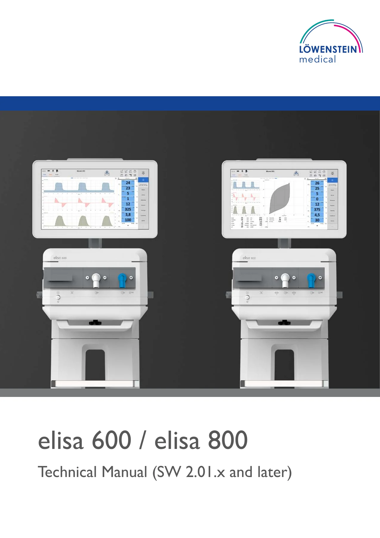
elisa 600 / elisa 800 Technical Service Manual - SW 2.01.x and Later PDF β€” PDF page 1 preview
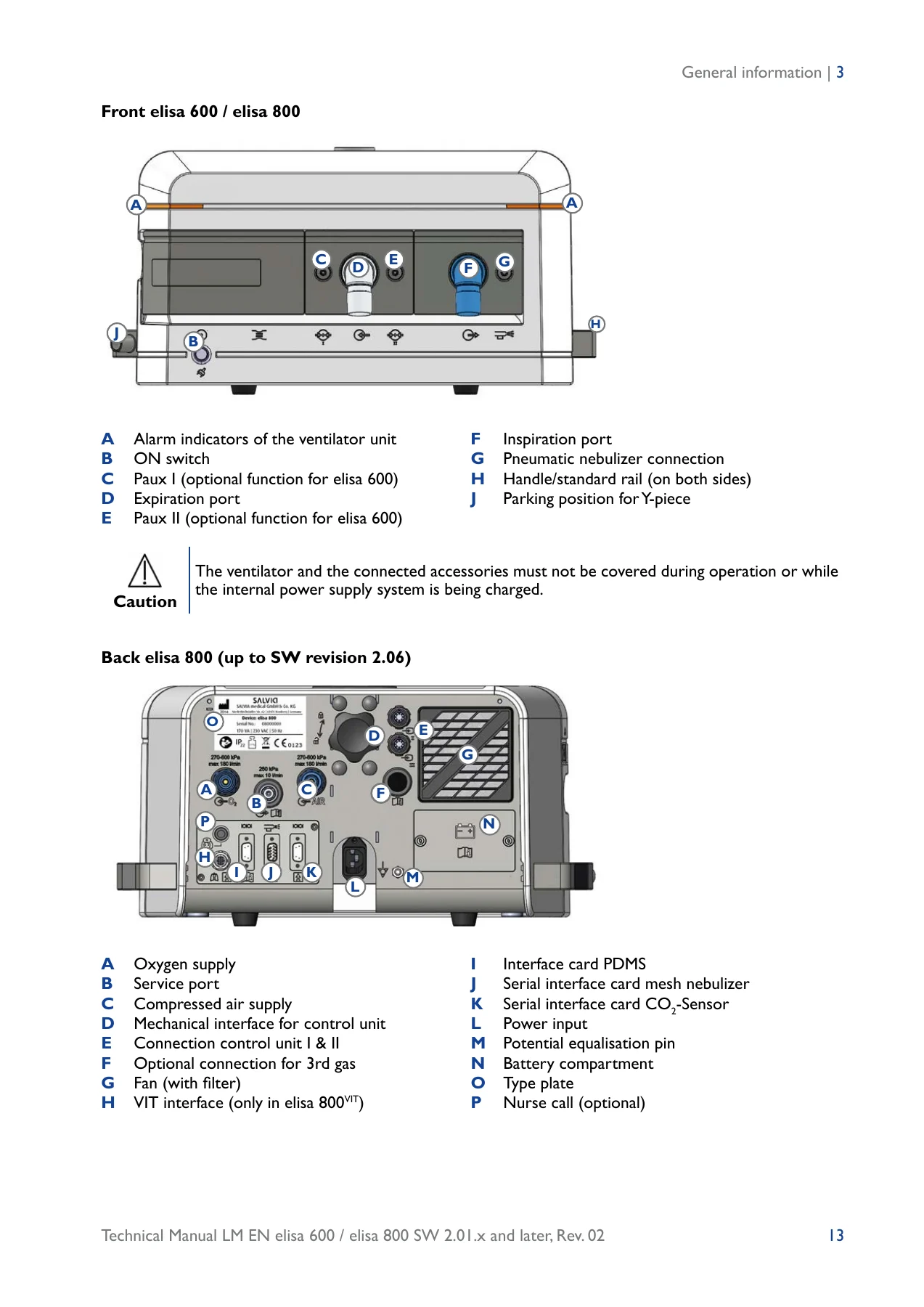
elisa 600 / elisa 800 Technical Service Manual - SW 2.01.x and Later PDF β€” PDF page 13 preview
elisa 600 / elisa 800 Technical Service Manual - SW 2.01.x and Later PDF β€” PDF page 37 preview

Instant PDF Delivery

The elisa 600 / elisa 800 Technical Service Manual is delivered as an instant-download PDF after checkout – no shipping, no waiting, no printed copy to lose on the ward. Open it on a laptop, tablet or phone, follow the procedures at the machine, and print only the pages you need in the workshop. Whether you are performing your first calibration on an elisa 800, chasing a #2073 expiratory flow alarm, or rebuilding a valve bar during a scheduled annual service, this PDF puts the correct procedure, correct numbers and correct part references directly in front of you.

Reviews

There are no reviews yet.

Be the first to review “elisa 600 / elisa 800 Technical Service Manual – SW 2.01.x and Later PDF”

What Our Customers Say

β˜…β˜…β˜…β˜…β˜… Live reviews from customers
Loading customer reviews...
0
    0
    Your Cart
    Your cart is emptyReturn to Shop
    πŸ›’
    Recently Purchased
    πŸ•’ verified order