Description
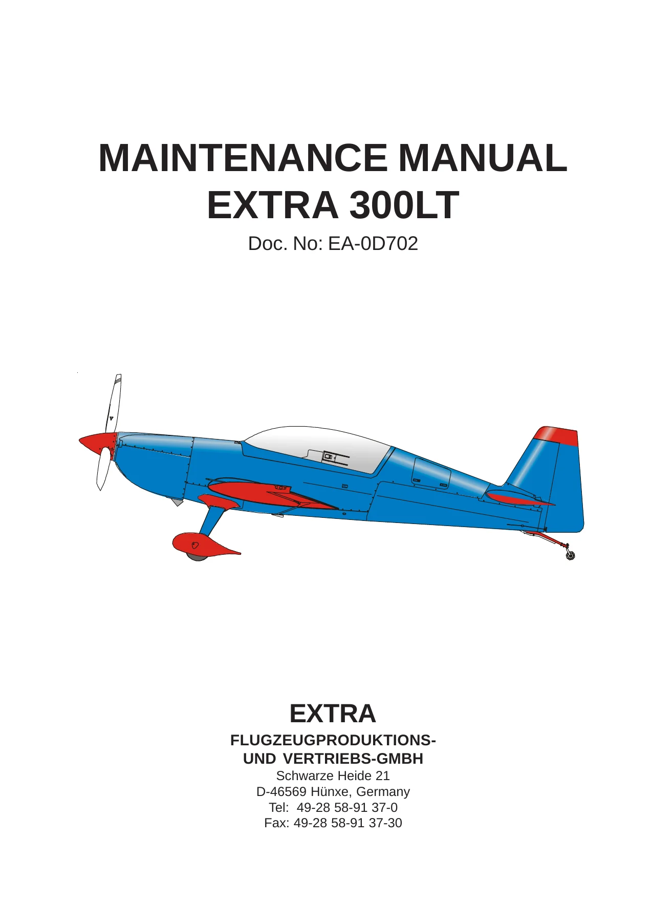
The Extra 300LT Maintenance Manual is the complete aircraft service and repair guide for the EXTRA 300LT aerobatic monoplane. Issued as Document No. EA-0D702, this 2nd Edition manual is dated 7 July 2010 and was approved under the authority of EASA DOA NΒ° EASA.21J.073. It covers every maintenance system on the aircraft, from airworthiness limitations and scheduled inspection intervals through to composite repair, flight controls, fuel, landing gear, propeller, powerplant and the Christen inverted oil system. Written for licensed maintenance personnel, it provides the procedures, torque values and inspection data needed to keep this high-performance two-seat aerobatic aircraft airworthy.
File Details
- Manual type: Aircraft Maintenance Manual
- Brand / model: EXTRA 300LT
- Document number: EA-0D702
- Edition: 2nd Edition (complete manual except Chapter 4)
- Date of issue: 7 July 2010
- Language: English
- Page count: 432 pages
- File format: PDF
Chapters Covered
- Chapter 1 β Introduction
- Chapter 2 β How to Use the Service Manual
- Chapter 3 β General Description (construction, flight controls, brakes, powerplant, fuel, electrical, instruments)
- Chapter 4 β Airworthiness Limitations (temperature limit, operating time, life limited components)
- Chapter 5 β Time Limits / Maintenance Checks (scheduled checks, lubrication charts, significant items inspection, unscheduled checks)
- Chapter 6 β Dimensions and Areas
- Chapter 7 β Lifting and Shoring
- Chapter 8 β Leveling and Weighing
- Chapter 9 β Towing and Taxiing
- Chapter 10 β Parking, Mooring, Storage and Return to Service
- Chapter 12 β Servicing (refueling, defueling, oil, brake fluid, tire inflation, cleaning)
- Chapter 20 β Standard Practices β Airframe (bolts, torque values, coin tapping, flexible hose, fittings, control cables)
- Chapter 21 β Air Conditioning (heating system, inlet box, distribution box, Bowden cables)
- Chapter 23 β Communication (VHF whip antenna)
- Chapter 24 β Electrical Power (battery, alternator, drive belt, circuit breakers, relays)
- Chapter 25 β Equipment and Furnishings (front and rear seats, seat belts, document bag)
- Chapter 27 β Flight Controls (aileron, rudder, elevator, trim tab, torque tube)
- Chapter 28 β Fuel (storage, distribution, indicating, selector valve, gascolator, boost pump)
- Chapter 31 β Indication / Recording System (instrument panels, stall warning)
- Chapter 32 β Landing Gear (main gear, tail spring, tail wheel, wheels and brakes)
- Chapter 33 β Lights (navigation/strobe, landing light)
- Chapter 34 β Navigation (pitot/static, altimeter, airspeed indicator, compass, transponder)
- Chapter 51 β Standard Practices and Structures β General (access panels, damage classification, materials, control surface balancing, repairs)
- Chapter 53 β Fuselage (canopy, main fuselage cover, bottom fuselage cover, cowling)
- Chapter 55 β Stabilizers (horizontal stabilizer, elevator, vertical stabilizer, rudder)
- Chapter 57 β Wings (wing removal/installation, ailerons)
- Chapter 61 β Propeller (governor, RPM vernier control cable)
- Chapter 71 β Power Plant (cowling, engine mount, shock mounts, air baffles)
- Chapter 72 β Engine (troubleshooting, removal/installation)
- Chapter 73 β Engine Fuel and Control (throttle, mixture, fuel pressure indicating)
- Chapter 77 β Engine Indicating (RPM, manifold pressure, CHT, EGT, MVP-50P)
- Chapter 78 β Exhaust (collector, muffler, gasket, heat shield)
- Chapter 79 β Oil System (Christen inverted oil system, oil cooler, oil pressure and temperature indicating)
Across these chapters the manual gives a complete picture of the EXTRA 300LT airframe and its systems. It opens with the general description and airworthiness limitations, then moves into the scheduled maintenance programme β 25, 50, 100, 200, 300, 400, 500 and 1000 hour checks, plus the 1000-hour Significant Items Inspection. From there each system is covered in turn: the steel-tube fuselage with its composite covers, the fibre-composite wing and stabilizers, the push-pull and cable flight control system, the hydraulically operated Cleveland disc brakes, the Lycoming AEIO-580-B1A engine installation with its Christen inverted oil system, the MT-Propeller three-blade constant-speed propeller, the fuel system with its center, acro and wing tanks, and the full electrical and indicating system. Repair guidance for composite and steel components, control surface balancing data and a comprehensive torque value section are also included.
Complete PDF Bookmark Tree
Complete Bookmarks
The complete bookmarks in the βExtra 300LT Maintenance Manual – Complete Aircraft Service & Repair Guide (Doc. EA-0D702)β are as follows:
Cover Pagep. 1
Intro Page A – Fp. 2
+CH01.pdfp. 10
01-00-00 GENERALp. 12
01-00-01 Trade Marksp. 15
01-10-00 SAFETYp. 16
+CH02.pdfp. 17
02-10-00 MANUAL DESCRIPTIONp. 19
02-10-01 Manual Set-Upp. 19
02-10-02 Chapter Set-Upp. 19
02-10-03 Page Numberingp. 20
02-10-04 Figure Numberingp. 20
02-10-05 Layoutp. 21
Figure 1 Layoutp. 21
02-10-06 Notes/Safety Notesp. 22
02-20-00 HANDLINGp. 23
02-20-01 Revisionsp. 23
02-20-02 Service Bulletinp. 24
02-20-03 Checklistsp. 24
02-20-04 Fax-Formatsp. 25
+CH03.pdfp. 26
03-00-00 GENERALp. 28
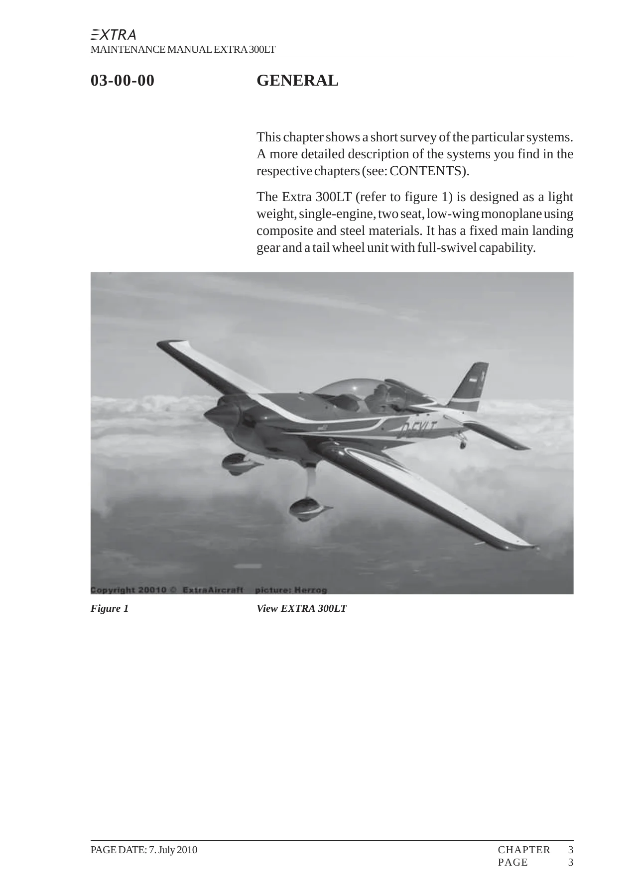
Figure 1 View EXTRA 300LTp. 28
03-10-00 DESCRIPTIONp. 29
03-10-01 Constructionp. 29
03-10-02 Flight Control Systemp. 29
03-10-03 Brake Systemp. 30
03-10-04 Powerplantp. 30
03-10-05 Fuel Systemp. 31
03-10-06 Electrical systemp. 31
03-10-07 Instrumentsp. 32
+CH04.pdfp. 33
04-00-00 Generalp. 36
04-00-01 Temperature Limitp. 36
04-00-02 Operating Timep. 36
04-10-00 Life Limited Componentsp. 38
04-10-01 Generalp. 38
04-10-02 Replacement Timep. 38
04-10-03 Service Life Limited Componentsp. 38
04-20-00 Major Inspectionp. 39
+CH05.pdfp. 40
05-00-00 GENERALp. 42
05-10-00 TIME LIMIT COMPONENTSp. 43
05-10-01 Generalp. 43
05-10-02 Overhaul Schedulep. 43
05-10-03 Recommended Replacement Timesp. 44
05-10-04 Time Between Inspectionp. 45
05-20-00 SCHEDULED Maintenance Checksp. 46
05-20-01 Generalp. 46
05-20-02 25 Hour Inspection – Enginep. 46
05-20-03 25 Hour Inspection – Aircraftp. 46
Figure 1 Drain and Vent Holesp. 47
Figure 2 Lubrication Chart 25 hoursp. 48
Figure 3 Lubrication Chart 50 hoursp. 49
Figure 4 Lubrication Chart 100 hoursp. 50
05-20-04 Maintenance Checks Schedulep. 51
05-20-05 Significant Items Inspectionp. 67
05-50-00 Unscheduled Maintenance Checksp. 76
05-50-01 Violent Stopping of the Engine (Propeller Strike)p. 76
05-50-02 Hard Landingp. 76
05-50-03 Engine Firep. 78
05-50-04 Lightning Strikep. 78
05-50-05 Flightline Inspectionsp. 79
+CH06.pdfp. 80
06-00-00 Generalp. 82
Figure 1 Axes and Planesp. 82
06-10-00 Main Datap. 83
06-10-01 Main Dimensionsp. 83
06-10-02 Wingp. 83
06-10-03 Horizontal Tailp. 84
06-10-04 Elevatorp. 84
06-10-05 Vertical Tailp. 84
06-10-06 Rudderp. 84
Figure 2 Three-View EXTRA 300LTp. 85
+CH07.pdfp. 86
07-10-00 Jackingp. 88
07-10-01 Balance Weightp. 88
Figure 1 Balance Weightp. 88
07-20-00 Shoringp. 89
07-20-01 Shoring the Frontp. 89
Figure 2 Shoring the Frontp. 89
07-20-02 Shoring the Tailp. 90
Figure 3 Shoring the Tailp. 90
+CH08.pdfp. 91
08-00-00 GENERALp. 93
08-10-00 Weighing and calculation of C of gp. 94
08-20-00 Levelingp. 97
Figure 1 Levelingp. 97
+CH09.pdfp. 98
09-00-00 GENERALp. 100
09-10-00 Towingp. 100
09-20-00 Taxiingp. 100
+CH10.pdfp. 102
10-00-00 GENERALp. 104
10-10-00 Parking/storagep. 105
10-20-00 Mooringp. 106
10-30-00 Return to servicep. 107
+CH12.pdfp. 108
12-00-00 GENERALp. 110
12-10-00 Replenishingp. 111
12-10-01 Refuelingp. 111
12-10-02 Defuelingp. 113
12-10-03 Fuel Drainsp. 113
12-10-04 Replenishment of Engine Oilp. 114
12-10-05 Oil Changep. 117
12-10-06 Replenishment of Brake Fluidp. 118
Figure 1 Replenishment of Brake Fluidp. 119
12-10-07 Tire Inflationp. 120
12-20-00 Scheduled Servicingp. 121
12-20-01 Exterior Cleaningp. 121
12-20-02 Interior Cleaningp. 122
12-20-03 Engine Cleaningp. 122
12-30-00 Unscheduled servicingp. 124
12-30-01 Removal of Snow and Icep. 124
+CH20.pdfp. 125
20-00-00 GENERALp. 127
20-10-00 Standard Practices Airframep. 128
20-10-01 Type of Boltsp. 128
20-10-02 Width Across Flats for Metric Boltsp. 130
20-10-03 Torque Valuesp. 131
20-10-04 Special Torque Valuesp. 132
20-10-05 Measuring Techniquesp. 133
20-10-06 Coin Tappingp. 133
Figure 1 Coin Tappingp. 133
20-10-07 Flexible Hosep. 134
20-10-08 Fittingsp. 135
20-10-09 Control Cablesp. 135
Figure 2 Control Cablesp. 139
20-20-00 ASSEMBLY INSTRUCTIONp. 140
20-20-01 Generalp. 140
20-20-02 Assembly Instruction after Container Shippingp. 140
+CH21.pdfp. 143
21-40-00 HEATINGp. 145
Figure 1 Heating System,p. 146
21-40-01 Inlet Boxp. 147
Figure 2 Heating Boxesp. 147
21-40-02 Distribution Boxp. 148
21-40-03 Main Bowden Cablep. 148
21-40-04 Distribution Bowden Cablep. 150
Figure 3 Heating Bowden Cablesp. 153
+CH23.pdfp. 154
23-10-00 Speech Communicationp. 156
23-10-01 VHF Whip Antennap. 157
Figure 1 Whip Antennap. 157
+CH24.pdfp. 158
24-00-00 Generalp. 160
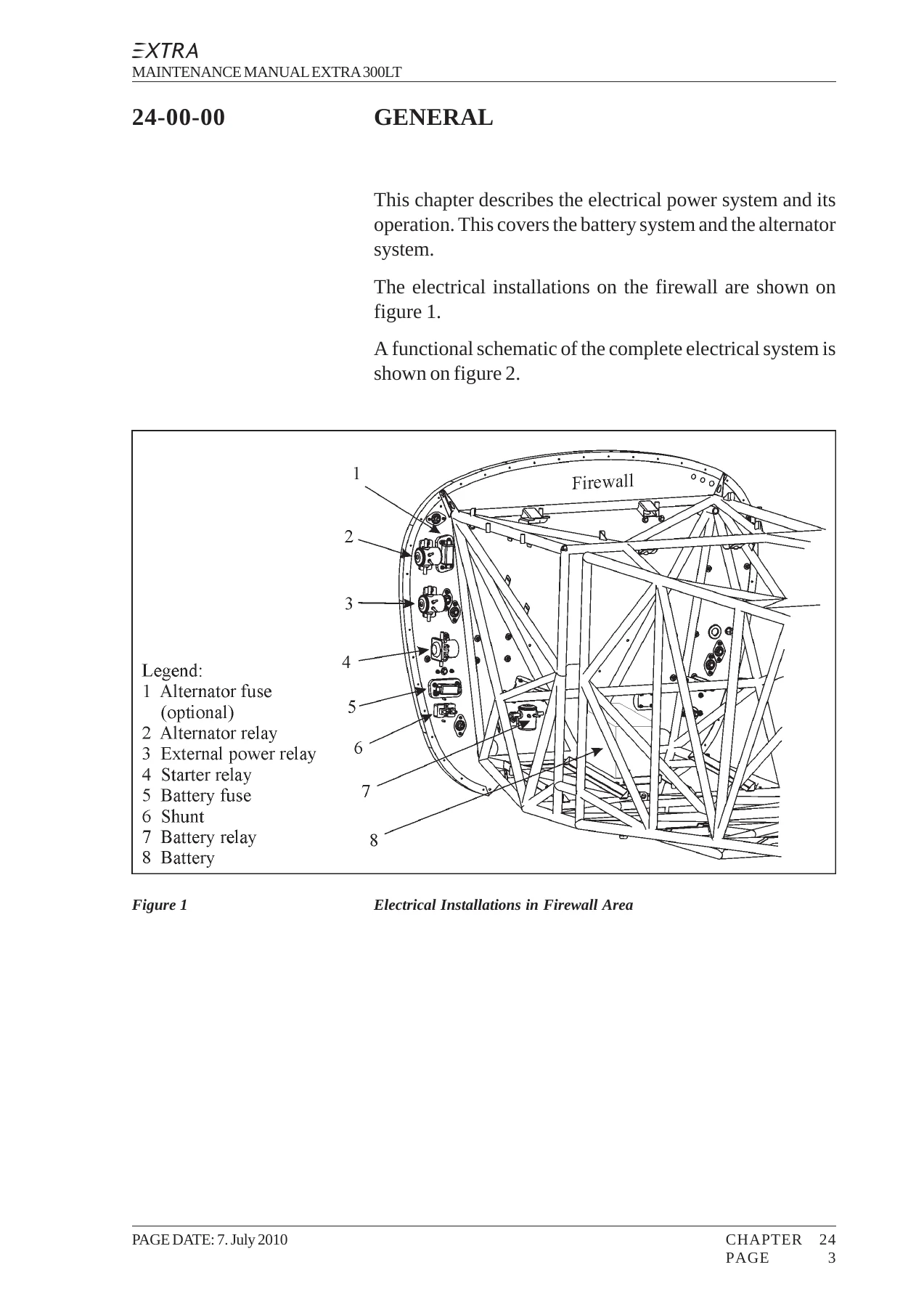
Figure 1 Electrical Installations in Firewall Areap. 160
Figure 2 Electrical System Schematicp. 161
24-30-00 DC-Generationp. 162
24-30-10 Battery Systemp. 162
24-30-11 Batteryp. 163
24-30-20 Alternator Systemp. 163
24-30-21 Alternatorp. 165
Figure 3 Alternator and Accessoriesp. 165
24-30-22 Drive Beltp. 167
24-30-23 Alternator Pulleyp. 169
24-30-30 System Groundp. 169
24-60-00 DC Electrical Load Distributionp. 170
24-60-01 Circuit Breakerp. 170
24-60-02 Toggle Switchp. 171
24-60-03 Subminiature Pushbotton Switchp. 171
24-60-04 Relayp. 171
+CH25.pdfp. 173
25-10-00 Flight compartmentsp. 175
25-10-01 Front Seatp. 175
25-10-02 Rear Seatp. 175
25-10-03 Seat Beltsp. 177
Figure 1 Strap Assemblyp. 177
Figure 2 Tubes for Shoulder Strap Attachmentp. 178
Figure 3 Shoulder Strap Attachmentp. 178
25-10-04 Aircraft Document Bagp. 179
+CH27.pdfp. 180
27-00-00 Generalp. 182
Figure 1 Controlsp. 182
Figure 2 Spacer Sleeve Displacedp. 183
Figure 3 Control Surface Mounting Aidp. 183
Figure 4 Control Surface Deflectionsp. 184
27-00-01 Control Rodsp. 185
Figure 5 Control Rod Measurementp. 186
Figure 6 Control Rod Identificationp. 186
Figure 7 Control Rod Check Holep. 187
27-00-02 Bellcranksp. 188
Figure 8 Control Levers and Rods Removal/Installationp. 188
27-00-03 Front Control Stickp. 189
Figure 9 Front Control Stick Removal/Installationp. 189
27-00-04 Rear Control Stickp. 190
27-00-05 Torque Tubep. 190
27-10-00 Aileron Controlp. 191
Figure 10 Aileron Controlp. 192
27-10-01 Aileronsp. 193
Figure 11 Trailing Edge Alignmentp. 194
27-10-02 Spadesp. 194
Figure 12 Spade Riggingp. 194
27-20-00 Rudder Controlp. 195
Figure 13 Rudder Controlp. 196
27-20-01 Rudderp. 197
27-20-02 Bottom Hinge Bracketp. 198
27-20-03 Bottom Hinge Bellcranksp. 198
27-20-04 Control Cablep. 198
27-20-05 Fairleadp. 201
27-30-00 Elevator Controlp. 202
Figure 14 Elevator and Trim Tab Controlp. 203
27-30-01 Elevatorp. 204
Figure 15 Neutral Position of the Rear Control Stickp. 205
27-30-02 Trim Tabp. 206
Figure 16 Trim Tab Riggingp. 207
+CH28.pdfp. 208
28-00-00 GENERALp. 210
Figure 1 Fuel Systemp. 211
28-10-00 Storagep. 213
Figure 2 Storagep. 214
28-10-01 Center Tankp. 215
28-10-02 Acro Tankp. 215
28-10-03 Acro Tank Flop Tubep. 216
Figure 3 Flop Tube Removal/Installationp. 216
28-10-04 Wing Tank Inspection Doorp. 217
Figure 4 Inspection Door Removal/Installationp. 217
28-10-05 Wing Tank Outletsp. 218
Figure 5 Wing Tank Outlets Removal/Installationp. 218
28-10-06 Center Tank Filler Neckp. 218
28-10-07 Wing Tank Filler Neckp. 219
28-10-08 Filler Neck Sealing Lipp. 219
Figure 6 Filler Neck and Sealing Lip Removal/Installationp. 220
28-10-09 Ventilation Linep. 220
28-20-00 Distributionp. 221
Figure 7 Distributionp. 222
28-20-01 Fuel Selector Valvep. 223
Figure 8 Fuel Selector Valve and Control Rodp. 224
28-20-02 Selector Valve Control Rodp. 225
28-20-03 Gascolatorp. 226
Figure 9 Gascolator Removal/Installationp. 226
28-20-04 Electrical Boost Pumpp. 227
Figure 10 Boost Pump Removal/Installationp. 227
28-20-05 Fuel Linesp. 228
28-40-00 Indicatingp. 229
Figure 11 Indicatingp. 230
28-40-01 Fuel Quantity Indicatorp. 231
28-40-03 Fuel Quantity Transducer (Center Tank)p. 232
28-40-04 Fuel Quantity Transducer (Wing Tank)p. 233
Figure 12 Fuel Quantity Transducer (Wing Tank) Removal/Installationp. 233
28-40-05 Float Wirep. 234
Figure 13 Float Wire Adjustmentp. 234
Figure 14 Float Wire Installationp. 235
+CH31.pdfp. 236
31-00-00 GENERALp. 238
31-10-00 Instrument and Control Panelsp. 239
31-10-01 Rear Instrument Panelp. 239
Figure 1 Rear Instrument Panelp. 240
Figure 2 Rear Switches & Circuit Breakersp. 240
31-10-02 Front Instrument Panelp. 242
Figure 3 Front Instrument Panelp. 242
Figure 4 Front Instrument Panel Removal/Installationp. 243
31-10-03 Rear Instrument Coverp. 244
Figure 5 Instrument Cover Removal/Installationp. 244
31-10-04 Typical Instrumentsp. 245
Figure 6 Typical Instrument Attachmentsp. 245
31-50-00 Central Warning Systemsp. 246
31-50-01 Stall Warning Systemp. 246
+CH32.pdfp. 247
32-10-00 Landing gearp. 249
Figure 1 Wheel Rake and Toe-inp. 249
32-10-01 Main Landing Gearp. 250
32-10-02 Top Half of the Mounting Clampp. 250
Figure 2 Main Landing Gear Mountingp. 251
32-10-03 Wheel Axisp. 251
32-10-04 Tail Springp. 251
32-10-05 Tail Wheel Forkp. 252
Figure 3 Tail Wheel, Fork and Springp. 253
32-40-00 Wheels and Brakesp. 254
Figure 4 Brake Systemp. 255
32-40-01 Master Cylinderp. 256
32-40-02 Wheel Fairingp. 257
Figure 5 Layer Sequence Wheel Fairingp. 257
32-40-03 Tail Wheelp. 258
+CH33.pdfp. 259
33-10-00 Flight Compartmentp. 261
33-10-01 Low Voltage Monitorp. 261
33-40-00 Exteriorp. 263
33-40-10 Navigation/Strobe Light Systemp. 263
33-40-11 Navigation/Strobe Lightp. 264
Figure 1 Navigation/Strobe Lights Removal/Installationp. 264
33-40-12 Strobe Light Power Supplyp. 265
Figure 2 Strobe Light Power Supply Removal/Installationp. 265
33-40-20 Landing Light Systemp. 266
33-40-21 Landing Lightp. 266
Figure 3 Landing Lightp. 267
33-40-22 Head Lampp. 268
33-40-23 Landing Light Power Supplyp. 268
+CH34.pdfp. 269
34-00-00 GENERALp. 271
34-10-00 Flight Environment Datap. 272
34-10-01 Pitot/Static Systemp. 272
Figure 1 Pitot/Static Drainp. 272
34-10-02 Altimeterp. 273
34-10-03 Airspeed Indicatorp. 273
34-10-04 Pitot-Static Tubep. 274
34-10-05 Pitot-Static Tube Attachment Blockp. 274
34-20-00 Attitude and Directionp. 276
34-20-01 Magnetic Compassp. 276
34-20-02 Attitude Indicatorp. 277
34-50-00 Dependent Position Determiningp. 278
34-50-01 Transponderp. 278
+CH51.pdfp. 279
51-00-00 Generalp. 281
51-00-01 Access Panel Identificationp. 281
Figure 1 Access Panel Identificationp. 282
51-10-00 Investigationp. 284
51-10-01 Damage Classificationp. 284
51-10-02 Repair Criteria and Limitsp. 285
51-30-00 Materialsp. 286
51-30-01 Composite Partsp. 286
51-30-02 Metal Componentsp. 291
51-30-03 Aluminium Componentsp. 292
51-30-04 Various Componentsp. 293
51-60-00 Control Surface Balancingp. 296
51-60-01 Weighing and Determination of Control Surface Momentsp. 296
Figure 2 Balancing Mandrelsp. 296
Figure 3 Determination of Control Surface Momentsp. 298
Figure 4 Control Surface Weights and Momentsp. 299
51-70-00 Repairsp. 300
51-70-01 Repair of Reinforced Glass and Carbon Fibre Componentsp. 300
51-70-02 Repair of Sandwich Materialp. 302
Figure 5 Minor surface damagep. 302
Figure 6 Curing cycle resin L20/SLp. 304
Figure 7 Level Sanding of Surrounding Areap. 304
Figure 8 Damage of Complete Sandwichp. 306
51-70-03 Repair of Laminatesp. 307
Figure 9 Repair of minor damagep. 309
51-70-04 Repair of Sparsp. 311
51-70-05 Structural Repair of Steel Componentsp. 311
51-70-06 Painting of Composite Partsp. 312
51-70-07 Aluminium and Steel Components Refinishingp. 313
+CH53.pdfp. 316
53-00-00 Generalp. 318
Figure 1 Fuselage Steel Tube Designp. 319
53-00-01 Canopyp. 320
53-00-02 Canopy Glassp. 320
Figure 2 Typical Cross Section of Canopy Bonding Areap. 320
Figure 3 Canopy Position Markingsp. 321
Figure 4 Canopy Tape Markingsp. 321
Figure 5 Canopy Adhesive Remaindersp. 322
53-00-03 Main Fuselage Coverp. 323
Figure 6, Sheet 1 Layer Sequence Main Fuselage Coverp. 324
Figure 6, Sheet 2 Layer Sequence Main Fuselage Coverp. 325
53-00-04 Bottom Fuselage Coverp. 326
Figure 7 Forward View on Bottom Side Firwallp. 326
Figure 8 Layer Sequence Bottom Fuselage Coverp. 328
Figure 9 Layer Sequence Cuffsp. 329
Figure 10 Layer Sequence Tail Fairingp. 330
Figure 11 Layer Sequence Top Half of the Engine Cowlingp. 331
Figure 12 Layer Sequence Bottom Half of the Engine Cowlingp. 332
+CH55.pdfp. 333
55-00-00 GENERALp. 335
55-10-00 Horizontal Stabilizerp. 336
Figure 1 Layer Sequence Horizontal Stabilizerp. 336
Figure 2 Horizontal Stabilizer Removal/Installationp. 338
55-20-00 Elevatorp. 339
Figure 3 Layer Sequence Elevatorp. 339
55-30-00 Vertical Stabilizerp. 340
Figure 4 Layer Sequence Vertical Stabilizerp. 340
Figure 5 Vertical Stabilizer Removal/Installationp. 342
55-40-00 Rudderp. 343
Figure 6 Layer Sequence Rudderp. 343
+CH57.pdfp. 344
57-00-00 Generalp. 346
Figure 1, Sheet 1 Layer Sequence Wingp. 347
Figure 1, Sheet 2 Layer Sequence Wingp. 348
Figure 1, Sheet 3 Layer Sequence Wingp. 349
57-00-01 Wingp. 350
Figure 2 Shims Installationp. 351
Figure 3 Wing Removal/Installationp. 353
57-60-00 Aileronsp. 354
Figure 4 Layer Sequence Aileronsp. 355
+CH61.pdfp. 356
61-00-00 GENERALp. 358
61-10-00 Propellerp. 359
61-20-00 Controllingp. 360
Figure 1 Controllingp. 360
Figure 2 RPM Vernier Control Cable Installationp. 361
61-20-01 Governorp. 362
61-20-02 RPM Vernier Control Cablep. 362
+CH71.pdfp. 365
71-10-00 COWLINGp. 367
Figure 1 Engine Cowlingp. 367
Figure 2 Landing Light Disconnection Plugp. 368
71-20-00 Engine Mountp. 369
Figure 3 Engine Mount & Shock Mount Installationp. 370
71-20-01 Shock Mountsp. 371
71-60-00 Air Bafflesp. 373
Figure 4 Air Bafflesp. 373
+CH72.pdfp. 375
72-00-00 GENERALp. 377
72-10-00 Enginep. 379
Figure 1 Lycoming Enginep. 379
+CH73.pdfp. 383
73-20-00 Controllingp. 385
73-20-10 Throttlep. 385
Figure 1 Throttle Controlp. 385
73-20-11 Throttle Control Cablep. 386
Figure 2 Firesleeve Lengthp. 387
73-20-12 Rear Throttle Control Leverp. 388
Figure 3 Throttle Control Leversp. 388
Figure 4 Throttle Control Cable Riggingp. 389
73-20-12 Front Throttle Control Leverp. 390
73-20-20 Mixturep. 390
Figure 5 Mixture Controlp. 391
73-20-21 Mixture Vernier Control Cablep. 391
Figure 6 Gap on Mixture Control Unit,p. 393
Figure 7 Mixture Vernier Control Cable Riggingp. 393
73-30-00 Indicatingp. 395
73-30-10 Fuel Pressurep. 395
Figure 8 Fuel Pressure Sense Linep. 396
73-30-11 Fuel Pressure Gaugep. 396
73-30-12 Sense Linep. 396
73-30-15 Fittingp. 397
+CH77.pdfp. 398
77-00-00 GENERALp. 400
Figure 1 Engine Sensor Locationsp. 400
77-10-00 Powerp. 402
77-10-10 RPMp. 402
77-10-11 Tachometerp. 402
77-10-15 RPM Sensorp. 402
77-10-20 Manifold Pressure (MAP)p. 402
77-10-21 Manifold Pressure Gaugep. 402
77-20-22 Sense Line Engine Compartmentp. 403
77-20-00 Temperaturep. 404
77-20-10 Cylinder Head Temperature (CHT)p. 404
77-20-11 Cylinder Head Temperature Gaugep. 404
77-20-12 CHT Sensorp. 404
77-20-20 Exhaust Gas Temperature (EGT)p. 405
77-20-21 Exhaust Gas Temperature Gaugep. 405
77-20-22 EGT Sensorp. 405
77-40-00 Integrated Engine Instrument Systemsp. 406
77-41-00 Electronics International MVP-50Pp. 406
Figure 2 Alternate Panel Layoutp. 408
77-41-01 Main Engine Screenp. 409
Figure 3 MVP-50P with Main Engine Screenp. 409
77-41-02 Mounting Sheetp. 410
77-41-03 Electronic Data Converterp. 410
77-41-04 Modulep. 410
Figure 4 Mounting Sheet and MVP-50P Componentsp. 411
77-41-05 Fuel Flow Transducerp. 412
Figure 5 Fuel Flow Transduverp. 412
77-41-06 Probes and Transducersp. 413
Figure 6 EGT/CHT Probes Locationp. 413
+CH78.pdfp. 414
78-00-00 GENERALp. 416
Figure 1 Exhaust Systemp. 416
78-10-00 Collector/Nozzlep. 417
78-10-01 Exhaust Pipep. 419
78-10-02 Mufflerp. 419
78-10-03 Gasketp. 420
78-10-04 Heat Shieldp. 420
Figure 2 Heat Shield Replacementp. 420
+CH79.pdfp. 421
79-00-00 GENERALp. 423
79-01-00 Christen Inverted Oil Systemp. 423
Figure 1 Inverted Oil System, Normal Flightp. 424
Figure 2 Inverted Oil System, Inverted Flightp. 425
79-01-01 Valve Ballsp. 426
79-20-00 Distributionp. 427
79-20-01 Oil Coolerp. 427
Figure 3 Oil Cooling Systemp. 428
79-20-02 Fittingsp. 428
79-20-03 Flexible Hosesp. 428
79-30-00 Indicatingp. 429
79-30-10 Oil Pressurep. 429
Figure 4 Oil Pressure Sensor & Wet Linep. 430
79-30-11 Oil Pressure Gaugep. 430
79-30-12 Oil Pressure Wet Linep. 430
79-30-13 Engine Fittingp. 431
79-30-20 Oil Temperaturep. 431
79-30-21 Oil Temperature Gaugep. 431
79-30-22 Oil Temperature Sensorp. 431
Figure 5 Oil Temperature Sensor Locationp. 432
Unbenanntp. 2
Unbenanntp. 2
Unbenanntp. 2
Unbenanntp. 2
What This Extra 300LT Manual Enables
This is not a general aerobatic aircraft book. It is the EXTRA 300LT service and repair manual as issued by the manufacturer, and it supports real maintenance work on this specific type. A technician can use it to plan and carry out the full scheduled inspection programme, to remove and reinstall the wing, stabilizers, flight controls, landing gear and engine, to rig the aileron, rudder and elevator systems, to adjust the trim tab, to bleed the brakes, to service the inverted oil system, to diagnose fuel and indicating faults, and to repair composite structure to the correct layer sequences and cure cycles.
The manual also contains the values that make the difference between a correct job and a dangerous one β control surface deflection tolerances, torque values for the main spar bolts and landing gear clamps, brake disc wear limits, tire pressure, fuel and oil capacities, composite temperature limits, and the life-limited component replacement times. For an aircraft used for aerobatics, where airframe and control system stresses are high, having these figures on hand is essential.
Who This Manual Is For
Licensed airframe and powerplant mechanics, aircraft maintenance organisations, owner-operators who maintain their own aircraft, and engineering students studying the EXTRA 300LT will all find this document directly useful. It is written for trained personnel who are already familiar with aircraft maintenance practice, and it assumes access to the relevant Lycoming, MT-Propeller, Christen, Cleveland and avionics vendor publications for component-level overhaul.
Get the Extra 300LT Maintenance Manual
Every procedure, tolerance and specification in this 432-page Extra 300LT aircraft service manual is delivered as an instant PDF download β no shipping, no waiting. Open it on a laptop, tablet or phone in the hangar, print the pages you need for the job at hand, and keep the complete document on file. Whether you are performing a routine 100-hour inspection, chasing an electrical fault, rebuilding a landing gear leg or repairing a composite panel, this Extra 300LT repair and maintenance guide gives you the manufacturer’s own instructions in one place.
Reviews
There are no reviews yet.