
GE Advantx R&F Positioner Schematics Manual – Direction 46-019095 Revision 11
Original price was: $34.95.$19.95Current price is: $19.95.
Complete GE Advantx R&F Positioner schematics service manual, Direction 46-019095 Revision 11. Full board-level schematics, block diagrams and signal lists for the RFP1 positioner cabinet, servo system, angulation drive, top interface and bus/CPU electronics.
Description
GE Advantx R&F Positioner Schematics Manual – Direction 46-019095 Rev 11
This is the GE Medical Systems Advantx R&F Positioner Schematics technical publication, issued as Direction 46-019095 Revision 11. It is the schematic-level reference for the Advantx R&F Positioner cabinet and its plug-in assemblies, written for service engineers who trace faults at the board, connector and signal-node level rather than working from generic repair steps. Every schematic sheet is paired with component value tables, signal name lists, and where applicable, board layouts and short circuit-theory summaries.
File Details
- Manual type: Schematics / Service Manual (Technical Publication)
- Brand / Manufacturer: GE Medical Systems (General Electric)
- Equipment covered: Advantx R&F Positioner
- Document number: Direction 46-019095
- Revision: 11
- Language: English
- File format: PDF
- Page count: 277
Chapters and Assemblies Covered
The manual is organised by assembly designator, which doubles as a location code inside the RFP1 cabinet. The full set of documented assemblies is:
- RFP1 A1 – Electronics Module
- RFP1 A2 – Angulation Drive Transformer Assembly
- RFP1 A3 – AC Power Distribution
- RFP1 A4 – Lateral Arm Drive
- RFP1 A5 – +5/+12 PS Remote
- RFP1 A6 – +5/+12 Power Supply
- RFP1 A7 – Table Angulation Motor Control
- RFP1 A8 – 26V Power Supply
- RFP1 A9 – Ion/Fld Lamp Power Supply
- RFP1 A10 – Cabinet Fans
- RFP1 A13 – Stepper Drive Transformer
- RFP1 A21 – Transition Assembly
- SF1A1 A2 / A3 / A4 – Servo Amplifier (three amplifier channels)
- SF1A1 A5 – Servo Controller
- SF1A1 A6 – Angulation and Top Interface
- SF1A1 A7 – Power Assist and Lock Control
- SF1A1 A8 – Coll Coil Ctl/Servo #1
- SF1A1 A9 – Coll Coil Ctl/Servo #2
- SF1A1 A10 – R&F Positioner Interface
- SF1A1 A11 – Stepper/Film Changer/Injector Interface
- SF1A1 A12 – Spare #1
- BIU – Bus Interface Unit
- S188 CPU – Central Processor board
- Multibus Interface PAL (PAL16R4) – Bus arbitration logic
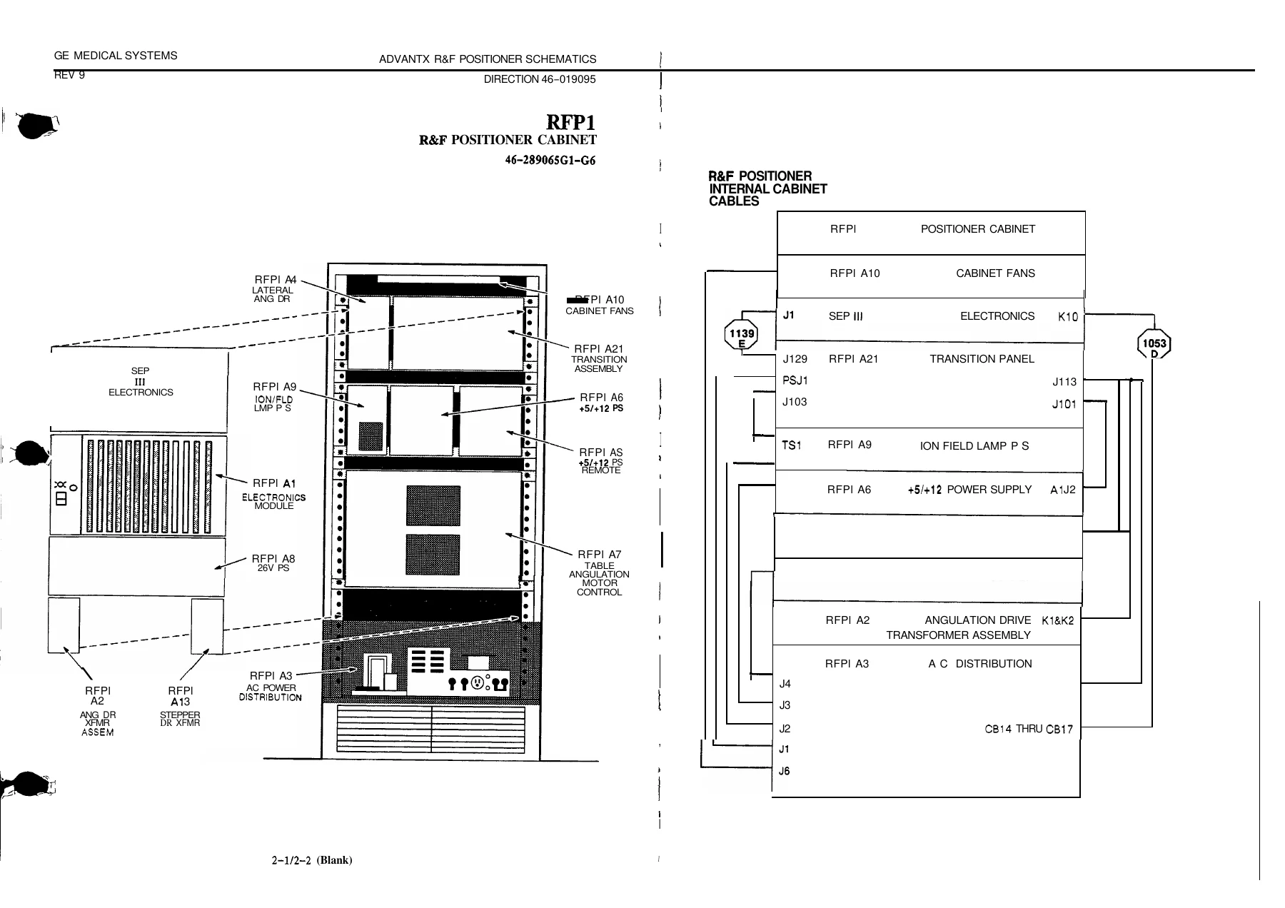
Beyond the assembly-level sheets, the manual documents the RFP1 Positioner Cabinet as a whole: the cabinet wiring reference (assembly 46-289065G1-G6), the positioner internal cabinet cables chart with connector J-designations, the R&F Positioner block diagram, and the AC distribution schematic. Signal tracing conventions are explained up front – schematics, signal lists and MIS maps are layered so that a node can be followed from a chip pin on a board, out through a connector, into a harness, and across the cabinet to the destination board.
What a Technician Gets From These Schematics
Working on an Advantx R&F Positioner without the correct sheets is effectively guesswork, because the system is distributed across plug-in cards, a backplane and multiple harnesses. This manual closes that gap in several specific ways:
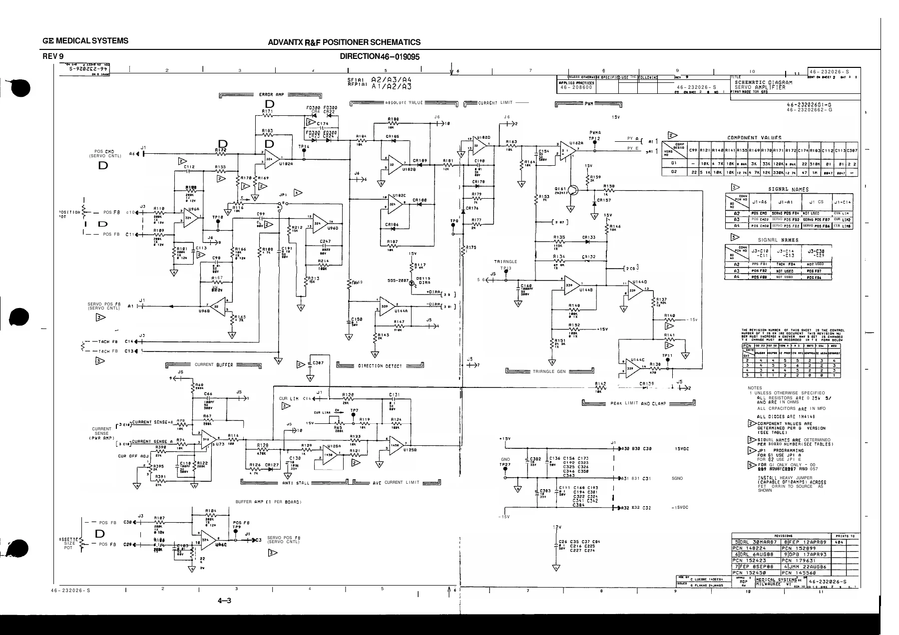
- Component-level schematics for every major circuit block, including the servo amplifier, servo controller, angulation/top interface, power assist and lock control, collimator coil control, positioner interface, stepper interface, the bus interface unit and the S188 CPU.
- Block diagrams that show how those sheets relate to one another, so a fault can be localised to a board before lifting a probe.
- Signal lists that identify the connector pins, terminals and test points wired to each node, with signal name cross-references from sheet to sheet.
- Component value tables beside each schematic – resistor, capacitor, diode and IC values – so the technician can verify parts without a separate parts catalogue.
- Board layout drawings that show where each U-number, resistor and test point actually sits on the PCB.
- Cabinet wiring reference for assembly 46-289065G1-G6, showing which harness runs to which J-connector.
- The Multibus Interface PAL (PAL16R4) with state diagram and timing waveforms, so bus arbitration faults on the S188 CPU can be traced against the actual timing rather than by substitution.
- MIS (Master Interconnect System) maps and charts referenced from the schematics binder, keeping major-assembly connections distinct from intra-board connections.
The scope is explicitly schematic – this is not a step-by-step repair manual. It is the reference the technician consults while performing the repair: to confirm pinouts before probing, to identify the correct board from a symptom, and to verify that a replacement part matches the original value. Safety content is limited to the multilingual warning pages at the front, which state that the manual must be consulted and understood before any service work begins.
Systems and Procedures the Sheets Support
Because the assemblies map directly to physical subsystems on the positioner, the manual supports work on the following:
- Positioner cabinet and internal cabinet cable routing
- Servo amplification for the drive motors
- Servo control and the closed-loop feedback path
- Table angulation drive and the angulation motor control
- Lateral arm drive
- Top interface between the positioner and the generator / imaging chain
- Power assist and lock control for manual positioning
- Collimator coil control and the ion/field lamp supply
- Stepper drive transformer and stepper interface for the film changer and injector
- Bus interface unit and Multibus backplane arbitration
- S188 CPU board including PAL control logic and cycle timing
- Low-voltage power distribution (+5, +12, 26V supplies and the +5/+12 remote sense line)
- AC power distribution inside the cabinet
How to Use the Sheets While Fault-Finding
The signal tracing section at the front of the manual sets out the intended workflow. Start at the sub-assembly schematic, take the signal name printed next to the node, and look the same name up in the signal list for that major assembly. The signal list gives every pin, terminal and test point that the node touches, including connections that leave the sub-assembly. If the signal crosses into another major assembly, the MIS maps carry it further. Signal names are not guaranteed to remain consistent across major assembly boundaries – the manual states this explicitly – so the technician must confirm the destination pin rather than trust the name. This is why the signal lists and cabinet wiring reference are as important as the schematics themselves.
Who This Manual Is For
This schematics manual is aimed at biomedical engineers and field service technicians who already know the Advantx R&F Positioner system architecture and need the board-level documentation to troubleshoot, verify a repair, or confirm a replacement part. It is equally useful for a workshop maintaining a single system in service and for an independent service provider who needs the GE-specified interconnect data rather than a generic positioner schematic.
Get the GE Advantx R&F Positioner Schematics Manual – Instant PDF
With the GE Advantx R&F Positioner Schematics Manual – Direction 46-019095 Revision 11 on hand, the technician can identify the correct board from a symptom, probe the right pin, read the correct component value, and verify that the harness on the positioner matches the documented interconnect. Correct schematics save diagnosis time on a machine where an incorrect substitution can damage a driver or a bus device, and where the distributed harness makes blind probing impractical.
IMAGES PREVIEW
This schematics manual is delivered as an instant PDF download after payment – no shipping, no waiting for a disc or a printed binder. The file opens on any laptop, tablet or desktop PDF viewer, and individual sheets can be printed and taken to the machine when working on site. Every schematic sheet, block diagram and signal list is reproduced in the same document, making it the single reference for positioner board-level service.
Reviews
There are no reviews yet.