
GE Healthcare Brivo OEC 715/785/865 Mobile C-Arm X-Ray Service Manual
Original price was: $49.95.$29.95Current price is: $29.95.
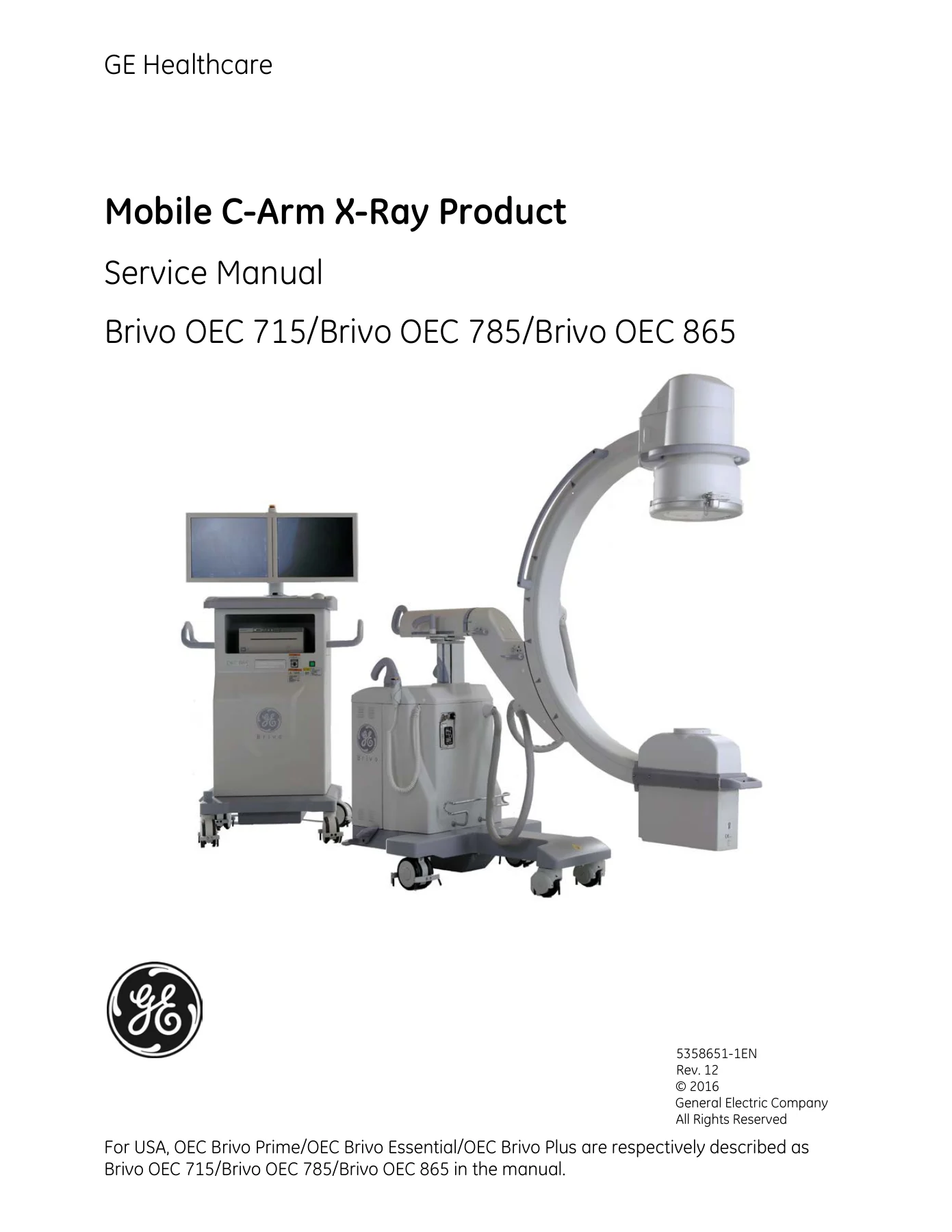
Complete GE Healthcare service manual for Brivo OEC 715, Brivo OEC 785, and Brivo OEC 865 Mobile C-Arm X-Ray systems. Covers installation, calibration, troubleshooting, replacement, periodic maintenance, and full system schematics.
Description
GE Healthcare Brivo OEC 715/785/865 Mobile C-Arm X-Ray Service Manual
This comprehensive service manual provides complete maintenance, calibration, troubleshooting, and repair guidance for the GE Healthcare Brivo OEC 715, Brivo OEC 785, and Brivo OEC 865 Mobile C-Arm X-Ray systems. Designed for field service engineers and biomedical technicians, the document covers every major subsystem—from the X-ray generator and image intensifier to the workstation, power distribution, imaging chain, and interconnect cabling.
File Details
- Manual Type: Service Manual
- Brand: GE Healthcare
- Models Covered: Brivo OEC 715, Brivo OEC 785, Brivo OEC 865
- Manufacturer: GE Hualun Medical Systems Co. Ltd
- Language: English
- Page Count: 529
- File Format: PDF
Chapters Covered
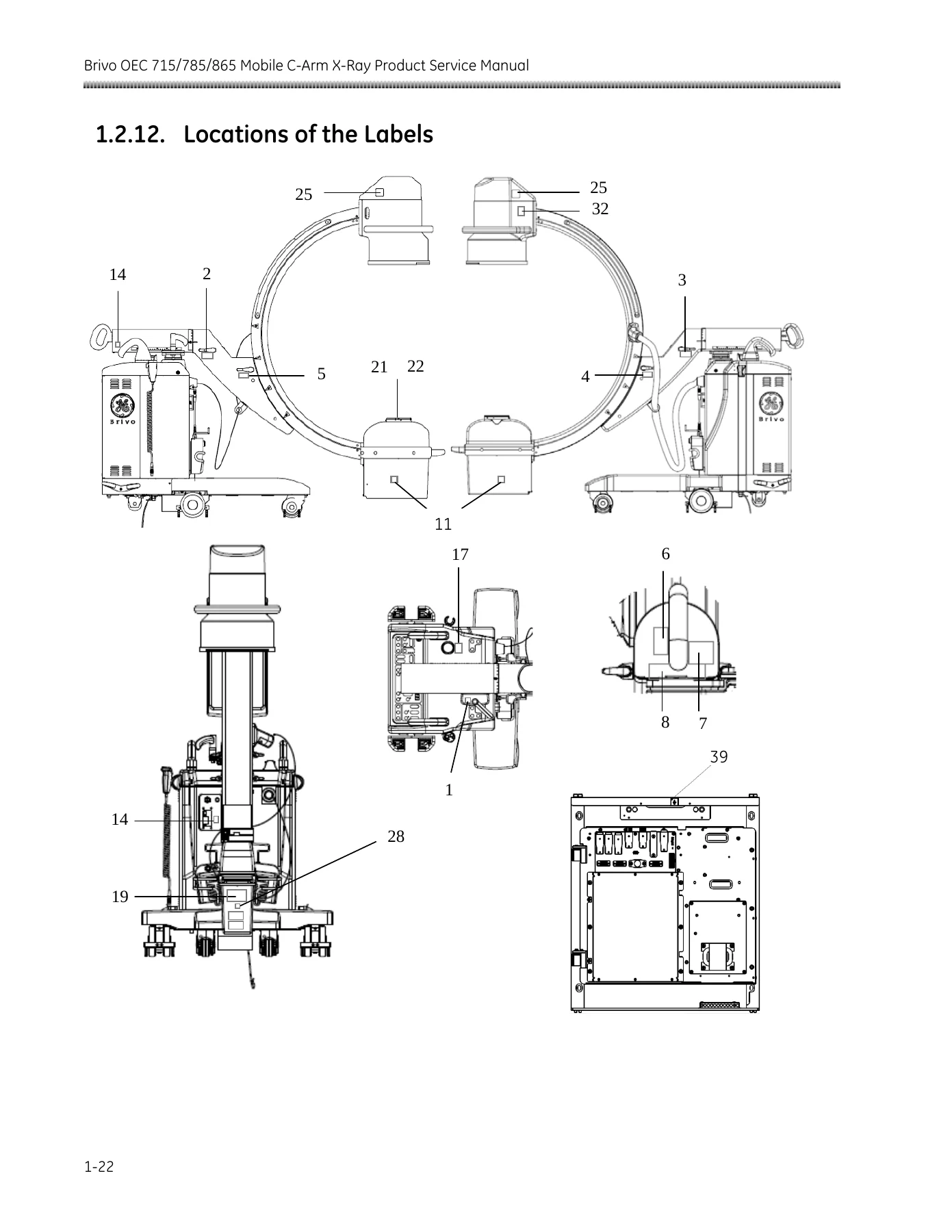
- Chapter 1: Introduction and Safety — Objective, Scope, Service Philosophy, Qualifications, Manual Organization; Safety Hazard Alerts, Ingress of Fluids, Electrical Shock, Explosion, Thermal Hazards, Equipment Stability, X-Radiation, Motorized Mechanical Movement, Lead Material Handling, Safety Interlocks, Labels, Symbols, Electromagnetic Compatibility Statement, Lock-Out/Tag-Out procedures.
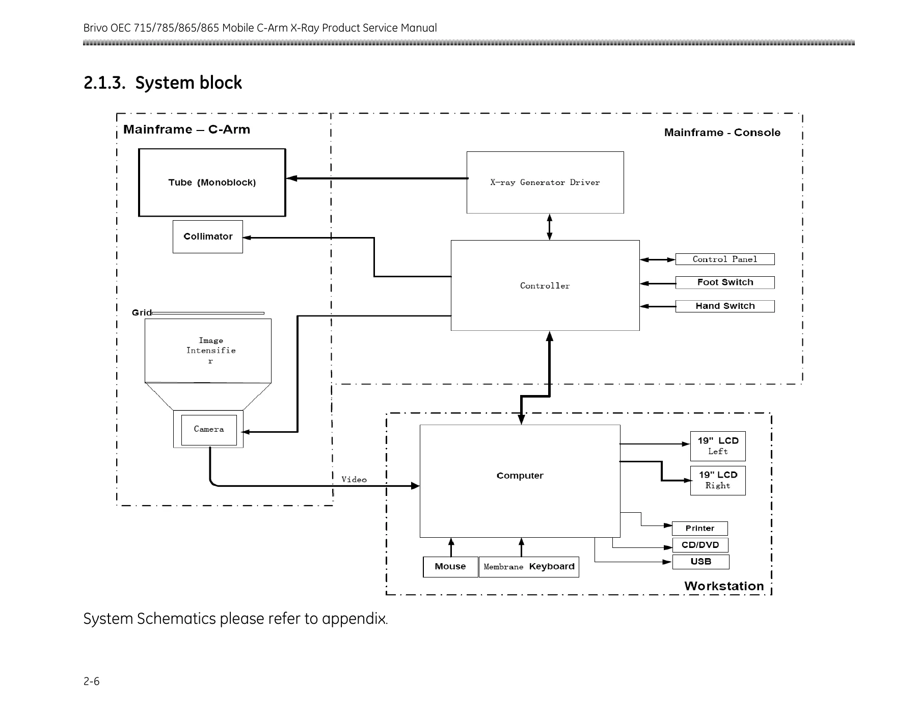
- Chapter 2: System Overview — System Descriptions, Component Locator, System Block Diagram; Subsystems: Power Distribution and Control, Mother Board, Mainframe Control Board, Display Board, Keyboard Control Board, Up/Down Board, System Interface Board, Collimator Control Board, kV Control and IGBT Assembly, Filament Driver Board, Monoblock, X-Ray/Key Switch and Emergency Switch, Image Chain (Collimator, Image Intensifier, GigE Camera, Anti-Scatter Grid, Monitor), Computer and Peripherals, UPS.
- Chapter 3: Installation — Pre-Installation requirements (dimensions, weights, site requirements, power supply, environment, tools); Unpacking procedures for C-Arm and Workstation; System Inspection (labels, external, internal); System Setup (power supply adaptation, UPS setup, system power on, admin interface configuration, DICOM setup and check, DICOM worksheet); Functional Checks (workstation, C-Arm, auto technique tracking, image resolution, dose limitation, beam alignment, DAP accuracy, system status backup); Options Installation (CD/DVD burner, laser aimer, video distributor, printers, film cassette holder, tube skin spacer, dual pedal footswitch, removal filter and sensor, removable grid, wireless DICOM, mono LCD monitor, software options, room interface); Installation Check List.
- Chapter 4: Calibration — kV Measurement and Adjustment; mA Measurement and Calibration; mAs Measurement and Calibration; X-Ray Generator Warm; Beam Alignment and Image Calibration (camera centering, BAFT/UBAT installation, collimator centering, collimator check and calibration, I.I. field size check and calibration, limiting field size, ABS tracking check and adjustment, limiting resolution, shading correction check and calibration); DAP Accuracy Verification and Calibration; Monitor Brightness and Contrast Adjustment; Power Input Tolerance Check.
- Chapter 5: Software — Service Tool (system information, configure product, calibration, exposure management, imaging processing config, maintenance, log viewer); Software Installation and Upgrade (operating system, application software); Firmware Upgrade (MCU firmware upgrade, CPLD upgrade).
- Chapter 6: Troubleshooting — Error Recovery Steps; Event Messages (structure of message code, definition of code, complete message list with diagnosis references); Troubleshooting Guide (workstation and control panel boot up display, shut down display, troubleshooting tree for boot up failure, X-ray failure, and no image failure).
- Chapter 7: Replacement — FRU List; Locations of FRU; Replacement procedures for system covers, brakes, handles, wheels, monoblock, collimator, PWAs (Collimator Control Board, Mainframe Control Board, Filament Drive Board, Mother Board, kV Control Board, IGBT Inverter Module, Up/Down Board, Power Distribution Unit Board, System Interface Board, Mainframe Control Panel Kit, Workstation Control Panel Kit), computer and peripheral parts, exposure indicator, monitors, CCD camera, image intensifier with power supply, image intensifier power supply, UPS, miscellaneous parts (rectifier bridge, drive power transformer, main transformer, start up transformer, DC power supply, DC bus capacitor, resonant capacitor, DC bus fuse, main power on breaker, C-Arm power filter, button and switch kit), interconnect cables, bundle cable, fuse kit, linear actuator, switches (hand switch, footswitch, emergency switch), and other options.
- Chapter 8: Periodic Maintenance — PM Checklist; Administrative Information; Safety Inspection (antistatic drag wires, electrical plug and power cord, interconnect cable and connector, footswitch cable and pins, ground continuity); PC Clean and UPS Performance Check; System Function Checks (power on, C-Arm mechanical movement, C-Arm controls, workstation checks, UPS battery performance); X-Ray Generator Accuracy Tests (kVp, mA, mAs); Image Quality Check (field size, auto technique tracking, image resolution, shading correction); Dose Check (dose rate, DAP accuracy); Reporting.
- Chapter 9: Technical Reference — System Specifications (safety classification, environmental requirements, power requirements, circuit breaker, earth leakage current, physical specifications); Specification of Key Components (X-Ray Generator, X-Ray Tube, X-Ray Tube Assembly, Collimator, Grid, Image Intensifier, Monitor, Digital Processor); Tube Rating Chart (filament emission characteristics, single load ratings, thermal characteristics); Radiation Safety Specification (scatter data, scatter radiation specification); Material Safety Data Sheets; Material Recycling.
- Appendix: System Schematics — Complete Interconnect Diagrams for Brivo OEC 715 (8 sheets), Brivo OEC 785 (8 sheets), and Brivo OEC 865 (8 sheets), including power distribution, system interface board, interlock loop, grounding, and fuse distribution diagrams.
This GE Healthcare Brivo OEC 715/785/865 Mobile C-Arm X-Ray Service Manual is the definitive technical resource for anyone responsible for maintaining, calibrating, or repairing these mobile C-arm imaging systems. The manual covers three model variants—the Brivo OEC 715, Brivo OEC 785, and Brivo OEC 865—providing model-specific information where differences exist, including image intensifier compatibility, grid specifications, camera types, and monitor configurations.
The troubleshooting chapter is particularly valuable, featuring a comprehensive event message list with hundreds of error codes, their meanings, and specific diagnostic references. Each error code is broken down by subsystem—X-ray control, imaging, application, and infrastructure—making it straightforward to trace a fault from the displayed code to the underlying cause. The troubleshooting trees for boot-up failure, X-ray failure, and no-image failure provide clear step-by-step decision paths that guide you from symptom to solution.
Calibration procedures are documented in exceptional detail. The kV calibration section walks through test point locations, oscilloscope settings, adjustment potentiometer identification, and verification tolerances. The mA calibration includes the preheat table calibration process with oscilloscope waveform analysis and convergence criteria. Beam alignment procedures cover camera centering for both Brivo OEC 715/785 and Brivo OEC 865 configurations, with specific screw locations and adjustment sequences. Collimator calibration is presented as a fourteen-step wizard-style process with measurement methods for iris diameter and shutter positioning. DAP calibration covers both with-filter and without-filter configurations, including dose coefficient calculation and accuracy verification.
The replacement chapter is equally thorough, providing calibration matrices that show exactly which calibration procedures must follow each FRU replacement. This prevents the common mistake of replacing a component and returning the system to service without performing the necessary recalibration. The compatibility matrix for image intensifier, camera, and grid combinations ensures you order and install the correct parts for each model variant. Torque specifications are provided for all fasteners, with special notes for aluminum alloy and aluminum casting thread holes.
Periodic maintenance procedures are designed for annual service visits, with a comprehensive PM checklist that covers safety inspection, PC maintenance, UPS performance verification, system function checks, X-ray generator accuracy tests, image quality checks, and dose verification. The first periodic maintenance is recommended after 13 months of use, then annually thereafter.
Technical reference data includes complete system specifications, environmental requirements, power requirements for all voltage configurations (100V through 240V), physical specifications with dimensions and weights, X-ray generator and tube specifications, collimator specifications, grid specifications for both OEC 715/785 and OEC 865, image intensifier specifications with central resolution values, monitor specifications, tube rating charts with filament emission characteristics and single load ratings, thermal characteristics, and scatter radiation data including dose contour plots and significant zones of occupancy measurements.
The appendix provides complete system schematics as interconnect diagrams for each model. These eight-sheet diagrams per model cover the power distribution unit, system interface board, computer connections, interlock loop, grounding, and fuse distribution. The interconnect diagrams show every connector, pin assignment, cable part number, and signal name—essential for tracing wiring faults and understanding system architecture.
Why This Service Manual Matters
Medical imaging equipment requires precise calibration, thorough maintenance, and correct repair procedures to ensure patient safety, diagnostic image quality, and regulatory compliance. The GE Healthcare Brivo OEC 715/785/865 Mobile C-Arm X-Ray Service Manual provides the manufacturer’s own procedures, specifications, and safety warnings—not generic advice or third-party approximations. From tube rating charts and thermal characteristics to scatter radiation data and electromagnetic compatibility information, every detail needed for correct service is documented.
For field service engineers, the troubleshooting and calibration chapters alone can dramatically reduce equipment downtime. The event message list with diagnosis references means you spend less time guessing and more time fixing. The calibration matrices ensure you complete every required adjustment after a component replacement. The FRU list and location diagrams help you identify and order the correct parts quickly. The periodic maintenance checklist ensures no critical inspection step is overlooked during scheduled service.
IMAGES PREVIEW
Instant PDF Delivery
This GE Healthcare Brivo OEC 715/785/865 Mobile C-Arm X-Ray Service Manual is delivered as an instant PDF download—no shipping, no waiting, no physical media to keep track of. Access the complete document on any computer, tablet, or smartphone. Print the specific pages you need for the service bay, or search the digital file for the error code or specification you need. The entire 529-page manual, including all chapters, diagrams, schematics, and appendices, is available immediately after purchase.



Reviews
There are no reviews yet.