

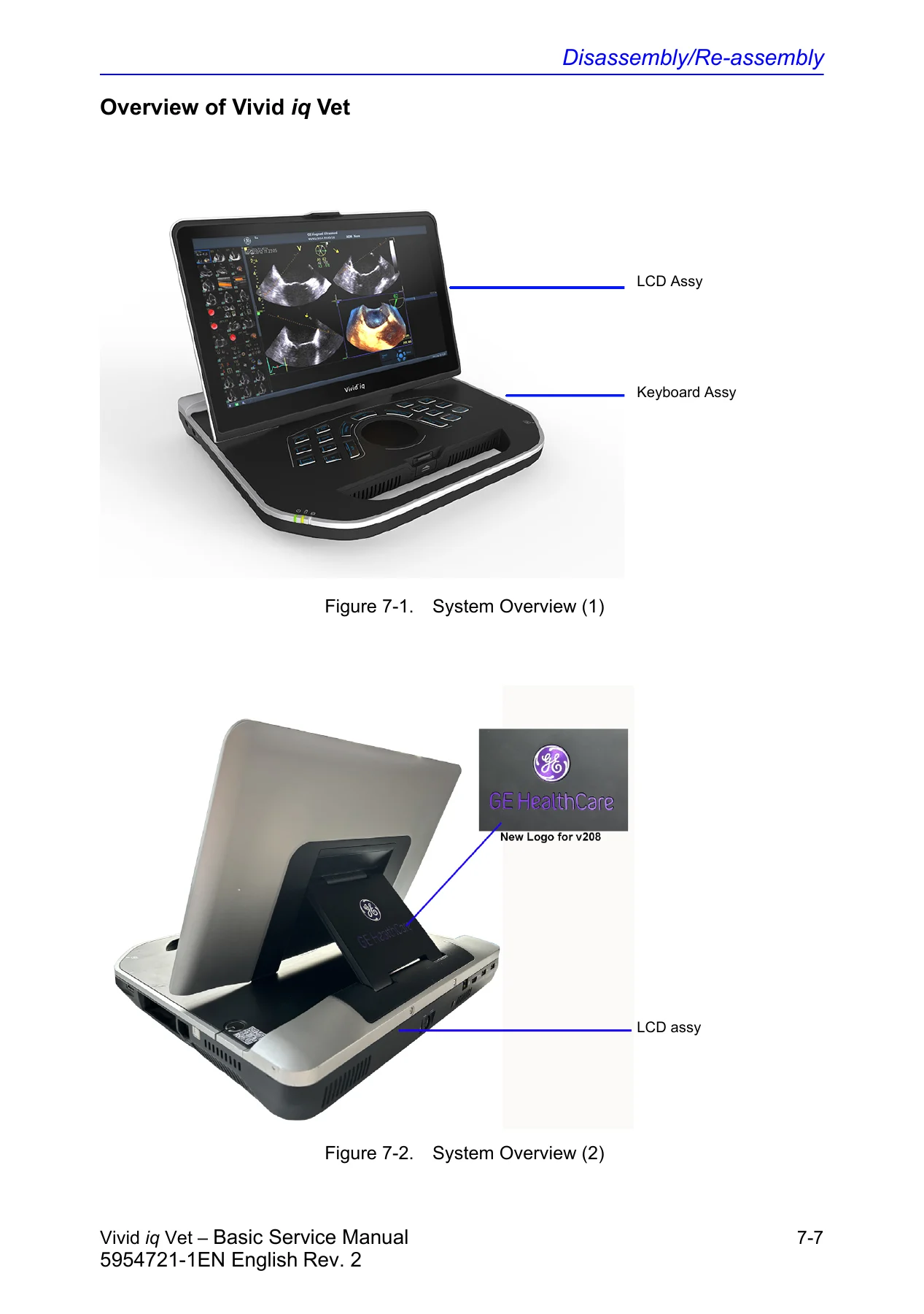
GE Vivid iq Vet v208 Ultrasound Basic Service Manual 5954721-1EN Rev 2
Original price was: $44.95.$26.95Current price is: $26.95.
The GE Vivid iq Vet v208 Basic Service Manual (Direction 5954721-1EN, Rev. 2) covers installation, setup, functional checks, diagnostics, replacement procedures and electrical safety testing for the veterinary ultrasound system. 517 pages in English.
Description
GE Vivid iq Vet v208 Basic Service Manual — Direction 5954721-1EN Rev. 2
This GE Vivid iq Vet Basic Service Manual is the full service-level reference for the Vivid iq Vet v208 ultrasound system. It applies to all versions of the 208.x.x software and is written for the service provider who must install, configure, verify, troubleshoot, repair and maintain the unit and its cart. The document carries Direction Number 5954721-1EN in English at Revision 2, dated 2024-08-30, and supersedes Rev. 1.
File Details
- Manual type: Basic Service Manual
- Brand: GE HealthCare
- Equipment: Vivid iq Vet v208 ultrasound system (and mobile cart)
- Language: English
- Page count: 517 pages
- File format: PDF
- Direction Number: 5954721-1EN
- Revision: Rev. 2
- Revision date: 2024-08-30
- Software coverage: All 208.x.x versions of the Vivid iq Vet software
Rev. 2 updates the battery information, updates the tutorial gesture section, removes the Tricefy section, adds content for Carto, adds part numbers for View-X and the Epiphan VGADVI Broadcaster, and adds a part number for the swiftlink cable. Those changes are useful to know if you are cross-checking a Rev. 1 copy.
Chapters Covered
- Chapter 1 — Introduction: overview, typical users, models covered, conventions and icons, label locations, human/mechanical/electrical safety, LOTO requirements, returning probes and repair parts, EMC/EMI/ESD, customer assistance, system manufacturer and authorised representative.
- Chapter 2 — Site Preparations: system environmental requirements, electrical requirements, EMI limitations, probe environmental requirements, facility needs, purchaser responsibilities, minimal and recommended floor plans, networking setup requirements, patient vicinity and patient environment definitions.
- Chapter 3 — System Setup: setup reminders and warnings, receiving and unpacking, packing materials and recycling, preparing for setup, completing setup, system configuration, Service Screen setup, peripherals installation, software options configuration, connectivity overview, v208 Connectivity setup (Network, Certificate, Proxy, View-X, View-X Direct, Imaging Insights, Data Streaming, Network Configuration, DICOM, Dataflow, Transfer, Buttons, Tools, Remote Path, Disk Management, Printer, Others), Disk Management Setup, paperwork after setup, CARTO 3 interface setup, and cart setup and cart using.
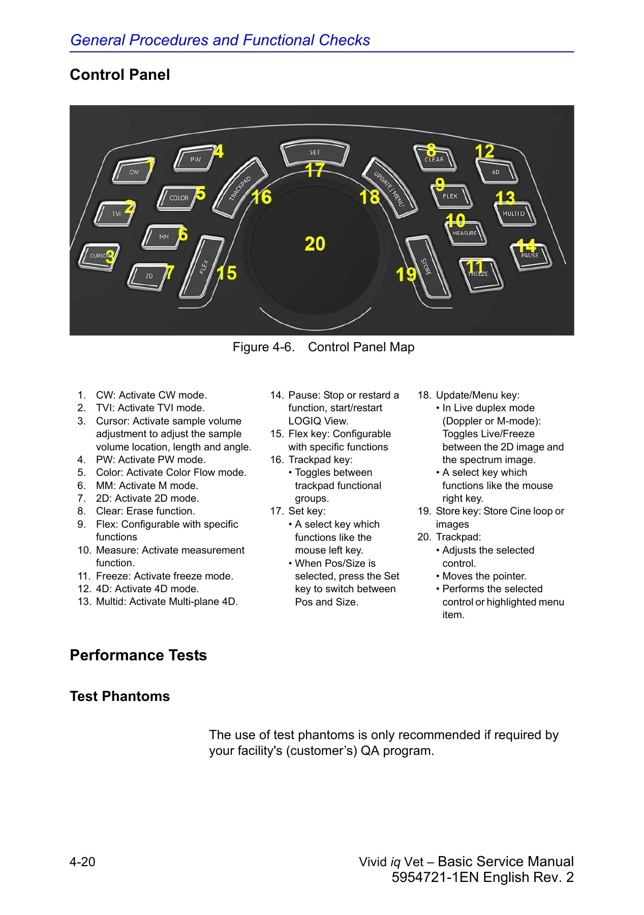
- Chapter 4 — General Procedures and Functional Checks: Power ON/Boot Up, powering off, charge box LED indicators, logging on as ADM, Service Key (SSA), removable media, creating and archiving presets, Data Management, backup, deleting patient information, restoring factory defaults, LCD monitor position adjustment, functional checks (Control Panel, 2D, M, Color, PW/CW, TVI, basic measurements, IQC preset, Probe/Connectors, ECG, Cineloop, Back End Processor, Operator Panel, Peripherals, Mechanical, Trackpad with Gesture), power supply test and adjustment, Application Turnover Check List and Site Log.
- Chapter 5 — Service Adjustments: LCD monitor adjustments, CARTO 3 interface description and connection overviews (Protocol 1.0 and Protocol 2.0), ICE catheter compatibility.
- Chapter 6 — Diagnostics/Troubleshooting: service safety, gathering troubleshooting data, screen captures, system warnings (temperature threshold, fan failure), Smart Service Interface (Disruptive mode, colour statuses, licences, Home, System Information, Software Status, Connected Probes, Utilities, Gather Logs, Delete Files, Change Password, Third Party Software Licences, SSA Licence, Network Capture, Data Transfer, Options, Agent Configuration), Asset Performance Management, Probe Check (auto and manual trigger, supported probes, cross-check flowchart), Insite II configuration, Setup Wizard, troubleshooting trees and battery status reading.
- Chapter 7 — Replacement Procedures: warnings and important information, tools needed, system overview, battery, rubber and cups, power box assembly, cart cable hook SVC kit, charge box, rubber and cups kit, back basket, front basket, printer shelf, USB cable for WIFI, loading the software from USB Flash Drive (UFD), verifying software versions and option keys, restoring patient archive and system configurations, loading application software only, and eDelivery software update.
- Chapter 8 — Renewal Parts: AC power cord list, CRU lists for console, generic cart and standard/premium cart, View-X/Epiphan VGADVI Broadcaster part numbers, probe list, ECG cables, accessories and printer tables, biopsy kits and manuals.
- Chapter 9 — Care and Maintenance: warnings, why maintenance matters, maintenance task schedule, tools required, system maintenance (preliminary checks, functional checks, physical inspection, optional diagnostic checks), probe maintenance, battery replacement and disposition, electrical safety tests (safety test overview, leakage current limits, outlet test, grounding continuity, chassis leakage current test, probe leakage current test, excess leakage diagnostics), inspection paperwork and electrical safety test logs, plus cart care and maintenance.
- Index: alphabetical index across all chapters.
What this manual gives a service technician is a complete top-to-bottom service reference. It starts with the pre-installation site survey and electrical requirements, walks through unpacking, connection, configuration and software option loading, then moves into the functional checks that verify a system is healthy after installation or repair. The diagnostics chapter is where the real troubleshooting work lives — log collection, screen capture, the Smart Service desktop, Probe Check integrity tests, Insite II remote setup and troubleshooting trees. The replacement chapter covers the field-replaceable items on the console and cart, and the electrical safety chapter gives the leakage current procedures and limits that a QA program or accreditation audit will ask for.
Coverage Highlights
Three v208 model designations are covered: H48232DM (Vivid iq Vet v208), H48232DN (Vivid iq Vet v208 Premium) and H48232DP (Vivid iq Vet v208 4D). When a procedure is not specific to one variant, the manual applies across all three. Electrical requirements are documented as 100–240 VAC ±10%, max 150 VA, 50/60 Hz. Console weight is listed as approximately 5 kg (11 lbs), and the cart system as 41 kg (90 lbs) or more depending on installed peripherals, with a full configuration ceiling of 65 kg (143 lbs) for the generic cart and 55 kg (121 lbs) for the standard/premium cart.
Connectivity coverage is extensive: the v208 Connectivity setup spans network screen, certificate import/delete, proxy configuration, View-X and View-X Direct, Imaging Insights, Data Streaming (with ConsultingPhys user-group authentication and PIN-code enrolment), DICOM setup, Dataflow types (Local Archive, DICOM Storage, Worklist, Query Retrieve), Disk Management and printer setup. If you are connecting a Vivid iq Vet to a hospital DICOM network or to a CARTO 3 system, this is the chapter that tells you which options must be installed, which ports must be open and how the dataflows map.
Diagnostics, Probe Check and Electrical Safety
The Probe Check section describes the probe element integrity test — the one that transmits on one channel at a time and records lens reflection while the probe scans in air. It lists the supported probes, the automatic trigger intervals (Every exam, 1 day, 7 days, 30 days, Never), the manual trigger from the probe menu, the failure dialog wording and the cross-check flowchart that a field engineer should follow if a probe test fails. The electrical safety chapter lists the leakage current limits by country and by applied part type (chassis, Type BF probe, Type CF ECG), the outlet wiring test, the grounding continuity test and the chassis and probe leakage current procedures, with blank data sheets for recording the readings.
Software Reload and Restoration
The software loading chapter describes both a full System + Application software load from USB Flash Drive and an Application-software-only load. It covers the BIOS entry (F7, password Renm@c5), the install prompts, the option key verification, the TCP/IP and DICOM re-verification, and the restore of the patient archive and system configuration. The Data Backup and Restore section gives the exact menu path (Config > Admin > Backup / Restore) and the caution that a restore overwrites the local hard drive.
Why This Manual Matters
The Vivid iq Vet is a compact, cart-mountable veterinary ultrasound system with a dedicated service lifecycle: setup, software options, network integration, functional checks, periodic electrical safety tests and field-replaceable parts. Doing any of those steps without the correct reference invites wrong firmware, mis-patched network connections, missed leakage current limits or unverified option keys. This manual supplies the specific values, procedures, part numbers and order-of-operations that the service task actually requires — from site floor plan to the option key entry screen to the probe leakage current pass/fail limit.
IMAGES PREVIEW
Instant PDF Delivery
The file is supplied as a PDF that you can open immediately after checkout, with no shipping and no wait for a physical book. It opens on any computer, tablet or phone that reads PDFs, and you can print the pages you need for the bench or the site visit. Whether you are a GE-trained field engineer, a hospital biomedical technician or an independent service provider working on a Vivid iq Vet, this is the single service reference that ties installation, configuration, diagnostics, repair and electrical safety together in one document.


Reviews
There are no reviews yet.