
John Deere 5055E 5065E 5075E 5078E 5085E 5090E Tractor Repair Manual TM801719
Original price was: $39.95.$24.95Current price is: $24.95.
Complete John Deere repair manual TM801719 for 5055E, 5065E, 5075E, 5078E, 5085E and 5090E tractors. Covers drive train, electrical, hydraulics, steering, brakes, differential, final drives and ROPS with torque specs, exploded views and step-by-step procedures.
Description
John Deere 5055E, 5065E, 5075E, 5078E, 5085E and 5090E Tractor Repair Manual – TM801719
This is the complete John Deere repair manual for the 5055E, 5065E, 5075E, 5078E, 5085E and 5090E tractors, published under document number TM801719 and dated 18JAN12. It is the technical manual a working technician reaches for when a John Deere E-series tractor needs a clutch replaced, a transmission torn down, a hydraulic hitch rebuilt, or a differential re-shimmed. Every group opens with a summary listing of essential tools, service equipment, service parts kits, specifications, wear tolerances and torque values for the job ahead, then walks through the repair in numbered steps with callouts keyed to photographs and line drawings.
File Details
- Manual type: Technical / Repair Manual
- Brand: John Deere
- Models covered: 5055E, 5065E, 5075E, 5078E, 5085E, 5090E
- Document number: TM801719
- Edition / date: 18JAN12 (English)
- Language: English
- Page count: 270
- File format: PDF
Chapters Covered
- Section 10 – General Information
- Group 05 – Safety (recognize safety information, understand signal words, handle fluids safely, prevent battery explosions, service cooling system safely, avoid high-pressure fluids, service tires safely, keep ROPS installed properly, dispose of waste properly)
- Group 10 – Service Recommendations (metric bolt and screw torque values, unified inch bolt and screw torque values, flat face seal fittings assembly and installation, metric face seal fitting torque charts, SAE face seal fitting torque charts, external hex plug torque chart)
- Section 40 – Repairing the Electrical System
- Group 05 – Battery, Starter Motor and Alternator
- Group 10 – Electrical System Components (air filter restriction sensor, coolant temperature sensor, engine speed sensor, fuel cut-off solenoid, engine oil pressure sensor, main key switch, tractor light switch, turn signal controller, instrument panel, PTO sensor, starter protection sensor, fuel level sensor)
- Group 15 – Wiring Harness (connector body replacement, WEATHER PACK connector, rear wiring harness W01, front wiring harness W02, cowl wiring harness W03, battery harness)
- Section 50 – Repairing the Drive Train
- Group 05 – Clutch Housing – TSS Transmission (separating engine from clutch housing, installing engine to clutch housing, replacing clutch housing retainer, clutch pedal inspection and adjustment)
- Group 10 – LUK Clutch Assembly (clutch housing seals, removing and installing clutch assembly, disassembling and inspecting, assembling clutch, adjusting drive clutch fingers, adjusting PTO clutch fingers)
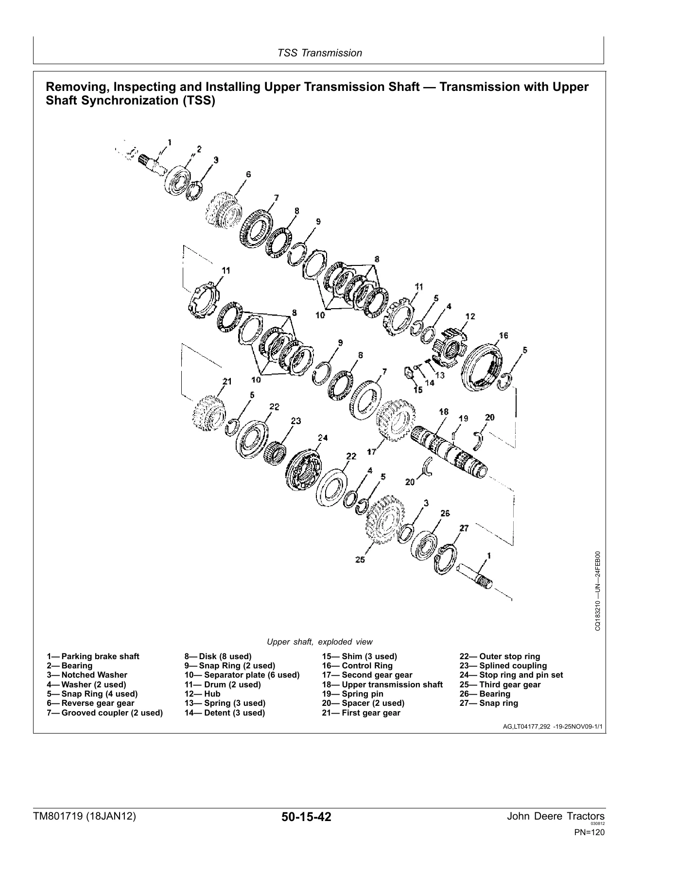
- Group 15 – TSS Transmission (separating clutch housing from transmission, installing clutch housing to transmission, shift lever removal and repair, transmission removal, disassembly and inspection, assembly, parking brake components, shifter shaft assemblies, upper transmission shaft with TSS synchronization)
- Group 20 – PTO Drive Shaft (PTO lever and link, rear PTO drive shaft assembly, PTO drive shaft assembly, 540/540E PTO)
- Group 25 – Differential (removing and installing differential assembly, disassembly, inspection and assembly, differential drive shaft, differential lock assembly, differential cone edge adjustment, play between differential teeth)
- Group 30 – Final Drives (final drive removal and installation, planetary drive assembly)
- Group 35 – Front-Wheel Drive Actuation (MFWD housing, MFWD drive shaft)
- Group 40 – Creeper Transmission (removing, installing, disassembling, assembling, bleeding brakes)
- Section 60 – Repairing Steering and Brakes
- Group 05 – Repairing the Steering (steering valve and column, disassembly and assembly, steering hydraulic lines with and without oil cooler)
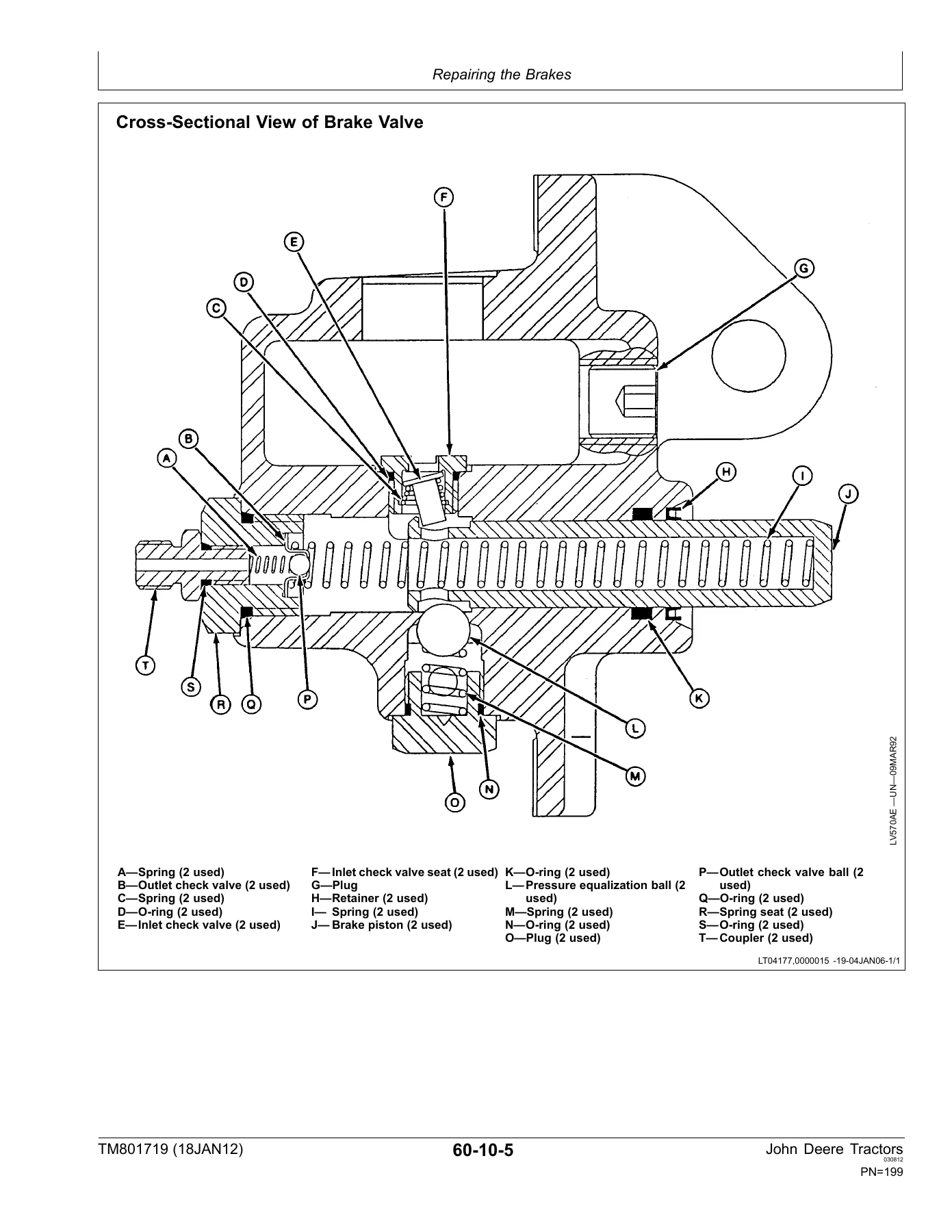
- Group 10 – Repairing the Brakes (brake valve and pedals, brake valve disassembly and assembly, brake removal and installation, brake hydraulic lines)
- Section 70 – Hydraulic Repair
- Group 05 – Hydraulic Pump and Filter (pump removal and installation, external pump components, disassembly, Bosch pump assembly, mesh filter, hydraulic filter/tubing, return and supply lines)
- Group 05B – Hydraulic Oil Cooler
- Group 10 – Hydraulic Hitch (control lever assembly, control mechanism, draft sensor support, main relief valve, overpressure relief valve, modulation valve, control valve without and with SCV, hitch housing, hitch arms, hitch cylinder and piston)
- Group 15 – Selective Control Valve (double SCV disassembly, inspection and assembly)
- Group 16 – Third Selective Control Valve (lever and link, removal and installation, disassembly, hoses)
- Section 80 – Mechanical Front-Wheel Drive
- Section 90 – ROPS (removing and installing roll-over protective structure)
- Section 100 – Special Tools (complete illustrated special tool listing including JDG1337 LUK clutch repair tool, JDG1375 clutch finger height tool, JDG19 assembly supports, JDG486 pinion clamp, JDG735 socket, JDT42 spring scale, DQ80699 final drive turning tool, KML10018 steering installation kit, JT07054 electrical isolator, JT07195B electrical repair kit, RE188114 parking brake adjustment tool)
What This Manual Gives a Technician
Section 50 alone is worth the price of entry on a John Deere E-series tractor. The LUK clutch assembly group walks through removing the clutch from the flywheel, disassembling the pressure plate, checking the PTO and drive clutch discs against their minimum thickness limits, assembling the pressure plate and disk spring back onto the clutch support plate, and adjusting drive and PTO clutch finger height with the JDG1375 gauge. The TSS transmission group takes the gearbox apart in the order a technician actually removes it – shifter shafts first, then forks and sleeves, then upper transmission shaft with the synchronizer assembly, range reduction shaft and driven shaft – and the assembly section rebuilds it in the exact reverse, with new retainers and O-rings and a parking brake ratchet adjustment that must be shimmed to 0.00-0.10 mm of play.
The differential group does not stop at disassembly. It covers the differential drive shaft setup in full: cone bearing preload set with a shim pack, initial turning drag measured with a cord and a spring scale, the locknut staked in place at 250 Nm, cone edge adjusted to 17.5 ± 0.05 mm, and play between the ring gear teeth checked with a comparing gauge to 0.18-0.25 mm. Final drive coverage continues in the same detail, including the planetary carrier with its 17 rollers per gear, and the heated bearing installation procedure with a strict 150 degrees C oil bath limit and the DQ80699 turning tool used to seat the roller bearings and verify turn torque.
Section 70 handles all hydraulic service. The Bosch tandem pump (system pump plus steering pump) is fully disassembled and reassembled with its seal rings, bearing assemblies and dowel pin alignment. The hydraulic hitch group covers the control lever assembly, control mechanism, draft sensor support, main relief valve, overpressure relief valve, rate-of-drop modulation valve, hitch control valve with and without SCV, hitch housing removal with the 82 kg weight warning, hitch arms, and the hitch cylinder and piston. Both the double SCV and the third SCV have their own group with full spool and detent service.
Electrical coverage in Section 40 goes sensor by sensor – coolant temperature, engine speed, fuel cut-off solenoid, oil pressure, air filter restriction, PTO, starter protection, fuel level – plus the main key switch, light switch, turn signal controller and instrument panel. The wiring harness group covers the rear harness (W01, in two versions for the 5055E/5065E/5078E/5085E/5090E and for the 5075E), the front harness (W02, likewise split), the cowl harness (W03) and the battery harness, along with WEATHER PACK connector replacement and installation using the JT07195B electrical repair kit and JDG364 extraction tool.
Why This Repair Manual Matters
Every group in this TM801719 repair manual opens with the torque values, wear limits and adjustment specs needed before work starts. The clutch assembly attaching bolts, the differential housing bolts, the final drive housing bolts, the ROPS mounting bolts, the hitch arm attaching nut, the differential drive shaft nut and dozens of others are all published to the newton-meter, and where a value has a tolerance it is spelled out. Friction surfaces are given minimum thicknesses. Cone edges, tooth play, rolling drag and shim packs are given target numbers. That is the difference between a repair that lasts and a repair that comes back.
Get It Instantly, Use It Anywhere
The John Deere 5055E, 5065E, 5075E, 5078E, 5085E and 5090E Tractor Repair Manual TM801719 is delivered as a PDF download the moment checkout completes – no shipping, no waiting on a courier. Open it on a laptop, tablet or phone in the shop, search across all 270 pages for a torque value or a procedure in seconds, and print only the pages you need on the bench. Whether you are pulling a transmission out of a 5075E, resealing a hydraulic pump on a 5055E, or shimming a parking brake on a 5090E, this is the reference that tells you what the factory service procedures actually are.
IMAGES PREVIEW


Reviews
There are no reviews yet.