★ TRUSTED BY 321,897+ PROFESSIONALS WORLDWIDE
🏢
Trusted Business
Verified & Licensed
🛡️
Virus Free Files
100% Safe Downloads
🔒
Secure Payment
SSL Protected
⚡
Instant Delivery
Available Immediately
Sale!

Kawasaki 115ZV-2 Wheel Loader Shop Manual – General Information, Functions & Structure (93216-00462)

Original price was: $44.95.Current price is: $26.95.

527-page Kawasaki 115ZV-2 wheel loader shop manual covering general information, chassis, power group, torque converter and transmission, hydraulics, brakes, electrical and operator station – function, structure, check and adjustment, plus full wiring and hydraulic diagrams for machines from S/N 9001 onward.

⚡
Instant PDF Download
Available immediately
💾
Save to Your Device
Download & keep forever
🛡️
Antivirus Scanned
100% virus-free
🌍
Trusted Worldwide
175,000+ customers

Description

Kawasaki 115ZV-2 Shop Manual – General Information, Functions & Structure

This is the Kawasaki 115ZV-2 wheel loader shop manual, document number 93216-00462, issued February 2017. It covers the machine’s general information, the function and structure of every major group, and the corresponding check and adjustment chapters, ending with the drawing and diagram section. Engine service is directed to the Cummins engine shop manual, but everything around the Cummins QSK19 – the chassis, driveline, transmission, hydraulics, brake system, electrical system and cab – is documented here.

File Details

  • Manual type: Shop / service manual (General Information, Functions and Structure)
  • Brand: Kawasaki
  • Model: 115ZV-2 wheel loader
  • Document number: 93216-00462
  • Date: February 2017
  • Language: English
  • Page count: 527
  • File format: PDF

Chapters Covered

  • 00 General Information – How to Use Manual, Safety Precautions, Symbols, Outline, Layout of Main Components, Inspection and Maintenance Table, Recommended Lubricants, Coolant, Lubrication Chart, Weight of Main Components, Bolt Tightening Torque, Hose Band Tightening Torque, Liquid Gasket and Screw Lock Agent, Cautions Regarding Welding Repair Service
  • 03 Measurement for Performance Check – Cautions on Safety, Standard Measurement Values for Performance Check
  • 12 Function & Structure Chassis Group – Front Chassis, Loading Linkage, Loading Linkage Pin, Rear Chassis, Fuel Tank, Floor Board Mount, Center Pin (Upper/Lower), Dust Seal
  • 13 Check & Adjustment Chassis Group – Linkage Pin, Liner, Adjusting Shim, Installing Bearing Cover, Installing Bearing Outer Ring
  • 22 Function & Structure Power Group – Power Line, Engine/Transmission Mount, Radiator (S/N 9001-9050 and S/N 9051-), Radiator Mount, Propeller Shaft (First, Second, Third), Axle Assembly, Axle Support, Differential Gear, Limited Slip Differential (option)
  • 23 Check & Adjustment Power Group – Measuring Engine Speed, Measuring Engine Oil Pressure, Propeller Shaft Phase and Alignment, Propeller Shaft Tightening Torque, Axle Nut Tightening Procedure, Differential Gear Adjustment Procedure, Bearing and Oil Seal Installation, Adjusting Tooth Contact
  • 32 Function & Structure Torque Converter and Transmission Group – Torque Converter Structure, Power Flow Path, Torque Multiplication, Lock-up Torque Converter (option), Gear Pump, Transmission, Clutch Combination, Planetary Gear, Shift Lever Positions, Downshift Button, Gear Train, Clutch Pack, Power Flow Paths, Hydraulic System and Circuit Diagrams, Modulator Valve Unit, Control Valve Assembly, Accumulator, Direct Charge Valve, Lock-up Clutch Solenoid Valve
  • 33 Check & Adjustment Torque Converter and Transmission Group – Clutch Oil Pressure and Time Lag, Measuring Clutch Oil Pressure
  • 42 Function & Structure Hydraulic Group – Flushing Hydraulic Circuit, Hydraulic Circuit Symbols, Hydraulic System Operation, Layout of Hydraulic Units, Hydraulic Tank (both S/N variants), Hydraulic Pump, Steering Pump, Loading System, Reducing Valve, Pilot Valve (S/N 9001-9100, 9101-9105, 9106-), Multiple Control Valve, Ride Control (option), Steering System, Orbitrol, Steering Valve, Stop Valve, Efficient Loading System, Fan Motor System, Reversing Fan Motor (option), Secondary Steering
  • 43 Check & Adjustment Hydraulic Group – Loading/Steering Circuit Relief Valve and Ride Control Reducing Valve, Hydraulic Cylinder, Stop Valve
  • 52 Function & Structure Brake Group – Brake System Outline, Brake Units Layout, Unloader Valve, Valve Unit, Accumulator, Brake Valve, Service Brake, Parking Brake, Parking Brake Manual Release, Brake Circuit Check Valve, Auto Brake, Pressure Sensors
  • 53 Check & Adjustment Brake Group – Brake Circuit Oil Pressure, Service Brake, Parking Brake
  • 62 Function & Structure Electrical Group – How to Use Electrical Wiring Diagram, Cable Color Codes, Circuit Symbols, Sensor Mount, Fuse and Fusible Link, Engine Start Circuit, Power Generating/Charging Circuit, ECM, Transmission Control Circuit and Monitor Circuit, Instrument Panel and Switch, MODM, Electrical Detent Circuit, Diodes
  • 72 Function & Structure Operator Station Group – Cabin, Glass, Wiper Mount, Wiper Motor, Operator Seat, Steering and Transmission Shift Lever, Air Conditioner (Denso system, cooling mechanism, electrical circuit, component functions, refrigerant charging), Troubleshooting
  • 73 Check & Adjustment Operator Station Group – Air Conditioner lubricating oil quantities, magnetic clutch air gap, compressor V-belt adjustment, periodic replacement parts
  • 92 Drawing & Diagrams – Axle Assembly, Torque Converter and Transmission, Hydraulic and Brake Circuit, Brake Circuit, Electrical Wiring Diagrams by serial range, Connector Views, Abbreviation Chart, Cabin and Air Conditioner Diagrams, Electrical Equipment Layout, MODM Operation

Complete PDF Bookmark Tree

Complete Bookmarks

The complete bookmarks in the “Kawasaki 115ZV-2 Wheel Loader Shop Manual – General Information, Functions & Structure (93216-00462)” are as follows:

Forewordp. 1
Safety Symbolsp. 2
CONTENTSp. 3
00 General Informationp. 15
How to Use Manualp. 16
Safety precautionsp. 16
Symbolsp. 17
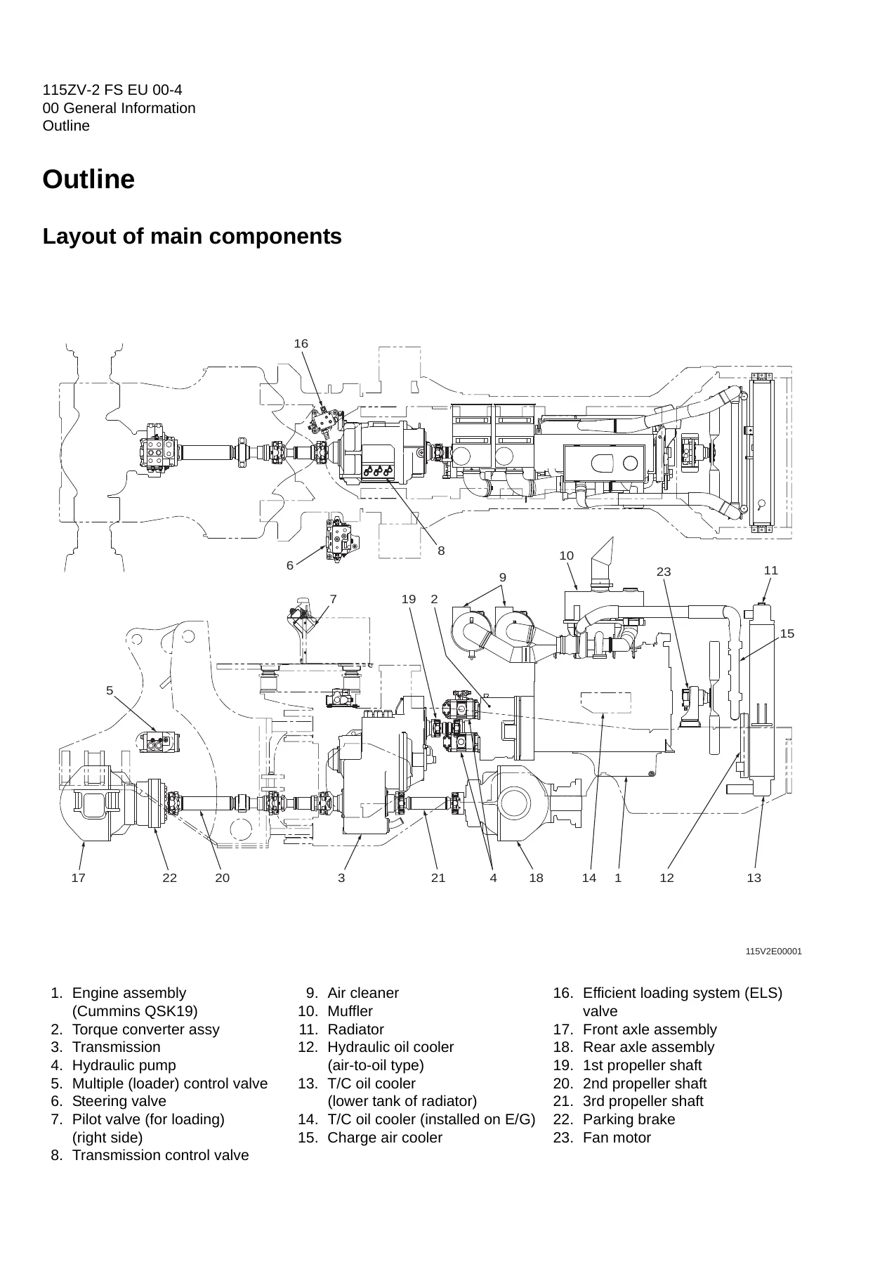
Outlinep. 18
Layout of main componentsp. 18
Inspection and maintenance tablep. 19
Recommended lubricantsp. 22
Coolantp. 23
Coolant specificationp. 23
Recommended mixture of antifreezep. 23
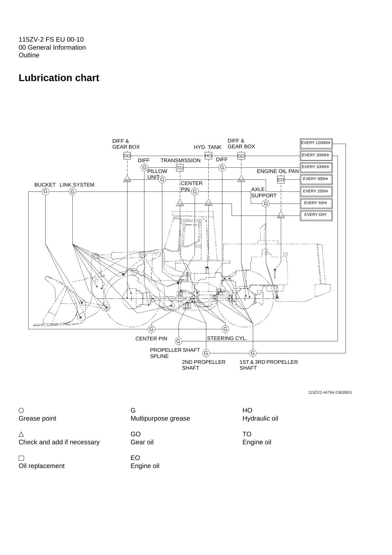
Lubrication chartp. 24
Weight of main componentsp. 25
Bolt tightening torquep. 26
Hexagon boltp. 26
Flanged hexagon boltp. 29
Hose band tightening torquep. 30
Liquid gasket and screw lock agentp. 31
Cautions regarding parts removalp. 31
Cautions regarding reassemblyp. 31
Screw lock agent application procedurep. 32
How to wind a seal tapep. 32
Cautions regarding welding repair servicep. 33
03 Measurement for Performance Checkp. 35
Cautions on Safetyp. 36
Standard Measurement Values for Performance Checkp. 37
12 Function & Structure Chassis Groupp. 41
Front Chassisp. 42
Loading linkagep. 42
Loading linkage pinp. 44
Rear Chassisp. 45
Fuel tankp. 45
Floor board mountp. 46
Floor boardp. 46
Viscous mountp. 46
Center Pinp. 47
Upper center pinp. 47
Lower center pinp. 48
Dust sealp. 49
13 Check & Adjustment Chassis Groupp. 51
Linkage Pinp. 52
Linerp. 52
Bucket hinge pin section (#1)p. 53
How to assemblep. 53
Bucket link pin section (#2)p. 54
How to assemblep. 54
Adjustmentp. 55
Center Pinp. 56
Adjusting shimp. 56
Installing bearing coverp. 56
Installing bearing outer ringp. 57
22 Function & Structure Power Groupp. 59
Power Linep. 60
Engine / Transmissionp. 61
Engine / transmission mountp. 61
Radiator (S/N 9001~9050)p. 62
Radiator mountp. 63
Radiator (S/N 9051~)p. 64
Propeller Shaftp. 66
First propeller shaft assemblyp. 67
Transmission – Torque converterp. 67
Second propeller shaft assemblyp. 68
Front differential – Transmissionp. 68
Third propeller shaft assemblyp. 69
Transmission – Rear differentialp. 69
Axle Assemblyp. 70
Axle Supportp. 72
Differential Gearp. 74
Conventional typep. 74
Function of differential gearp. 77
Power transmissionp. 77
Operation of differential gearp. 77
Straightp. 77
Turnp. 78
Limited Slip Differential (option) (S/N 9054~)p. 79
LSD structurep. 79
LSD functionp. 80
LSD operationp. 80
23 Check & Adjustment Power Groupp. 81
Enginep. 82
Measuring engine speedp. 82
Measuring engine oil pressurep. 82
Propeller Shaftp. 83
Propeller shaft phasep. 83
Second propeller shaft alignmentp. 83
Propeller shaft tightening torquep. 84
Axlep. 85
Axle nut tightening procedurep. 85
Differential gear adjustment procedurep. 86
Preload adjustmentp. 87
Bearing installationp. 88
Oil seal installationp. 88
Adjusting tooth contactp. 89
32 Function & Structure Torque Converter and Transmission Groupp. 91
Torque Converterp. 92
Torque converter structurep. 93
Power flow pathp. 93
Torque multiplicationp. 93
Torque Converter (Lock-up) (Option)p. 94
Lock-up clutch structurep. 95
Lock-up clutch function (only forward)p. 95
Automatic shift (with lock-up solenoid)p. 96
Torque Converter Gear Pumpp. 97
Gear pump specificationsp. 97
Transmissionp. 98
Clutch combinationp. 99
Planetary gearp. 99
Shift lever positionp. 99
Downshift button operationp. 99
Gear train and number of teethp. 100
Clutch specificationsp. 100
Friction plate: mm (in)p. 101
Steel plate: mm (in)p. 102
Clutch Packp. 104
Power Flow Path in the Transmissionp. 105
Forward 1st speed power flow pathp. 105
Forward 2nd speed power flow pathp. 106
Forward 3rd speed power flow pathp. 106
Forward 4th speed power flow pathp. 107
Reverse 1st speed power flow pathp. 107
Reverse 2nd speed power flow pathp. 108
Reverse 3rd speed power flow pathp. 108
Hydraulic System Diagramp. 109
Hydraulic Circuit Diagramp. 110
Oil Flowp. 112
Oil flow in the torque converter linep. 112
From torque converter gear pump to torque converterp. 112
From torque converter to cooling circuitp. 112
From cooler to lubrication circuitp. 112
Oil flow in the transmission linep. 112
From torque converter gear pump to clutch solenoid valve assemblyp. 112
From clutch solenoid valve to clutch valve assemblyp. 112
From torque converter gear pump to lock- up clutch (option)p. 112
From accumulator to clutch valvep. 113
Limit switchp. 113
From direct charge valve to clutch valvep. 113
T/C and T/M Oil Circulationp. 114
Modulator Valve Unitp. 115
Interior schematic (simple explanation)p. 117
Modulation Mechanismp. 118
Modulator valve functionp. 118
Modulator valve operationp. 119
Control Valve Assemblyp. 121
Clutch solenoid valve assemblyp. 123
For high, low, reverse and speed clutchesp. 125
Clutch valve assemblyp. 126
Accumulator assemblyp. 127
Accumulator structurep. 127
Direct charge valvep. 128
Lock-up clutch solenoid valvep. 129
33 Check & Adjustment Torque Converter and Transmission Groupp. 131
Clutch Oil Pressure and Time Lagp. 132
Measuring clutch oil pressurep. 132
Clutch oil pressure measurement procedurep. 133
Time lag measurement procedurep. 134
42 Function & Structure Hydraulic Groupp. 135
Flushing Hydraulic Circuitp. 136
Purpose of flushingp. 136
Cautions on Hydraulic Parts Replacementp. 137
Hydraulic Circuit Symbolsp. 138
Hydraulic linesp. 138
Pumps & motorsp. 138
Cylindersp. 138
Operation methodsp. 139
Pressure control valvep. 139
Flow control valvep. 139
Directional control valvep. 140
Check valvep. 140
Miscellaneous hydraulic symbolsp. 141
Hydraulic System Operationp. 142
Hydraulic system operation outlinep. 142
Loading systemp. 142
Steering systemp. 142
Efficient loading systemp. 143
Fan motor systemp. 143
Ride control system (OPT)p. 143
Layout of Hydraulic Unitsp. 144
Hydraulic Tankp. 145
Hydraulic Tank (S/N 9001~9150)p. 145
Hydraulic tank breather valve (tank cap) (S/N 9001~9150)p. 146
Hydraulic Tank (S/N 9151~)p. 147
Hydraulic tank breather valve (tank cap) (S/N 9151~)p. 148
Hydraulic tank specificationsp. 149
Hydraulic oil level checkp. 150
Hydraulic Pumpp. 151
Loading and pilot and brake pumpp. 151
Pump specificationsp. 151
Steering pumpp. 152
Steering pump specificationsp. 152
Hydraulic pump principlep. 153
Hydraulic pump wear platep. 154
Hydraulic pump bushing lubricationp. 154
Hydraulic Cylinderp. 155
Boom cylinderp. 155
Bucket cylinderp. 155
Steering cylinderp. 156
Hydraulic cylinder specificationsp. 157
Loading Systemp. 158
Reducing Valve (for Pilot Pressure)p. 159
Pilot valve (S/N 9001~9100)p. 160
Pilot valve functionp. 162
Pilot valve operation (modulated position)p. 162
Pre-detent and detent magnet solenoidp. 164
Pilot valve (S/N 9101~9105)p. 165
Pilot valve functionp. 167
Pilot valve operation (modulated position)p. 167
Pre-detent and detent magnet solenoidp. 169
Pilot valve (S/N 9106~)p. 170
Pilot valve functionp. 172
Pilot valve operation (modulated position)p. 172
Pre-detent and detent magnet solenoidp. 174
Multiple Control Valve (KML35A/2T103)p. 175
Multiple control valve specificationsp. 176
Multiple control valve main relief valvep. 177
Main relief valve operationp. 177
Adjusting set pressurep. 178
Multiple control valve overload relief valve (with make-up function)p. 179
Overload relief valve operationp. 179
Make-up valve operationp. 180
Multiple control valve make-up valvep. 180
Make-up valve operationp. 180
Multiple control valve bucket spoolp. 181
Bucket spool operationp. 181
Multiple control valve boom spoolp. 183
Boom spool operationp. 183
Adapter (Orifice)p. 186
Ride Control (OPT)p. 187
Ride control hydraulic circuitp. 187
Ride control functionp. 187
Ride control operationp. 188
Preparation mode (ride control switch is OFF)p. 188
Running mode (ride control switch is ON)p. 189
Ride control valve assembly (Reducing valve circuit)p. 190
Reducing valvep. 191
Check valvep. 191
Solenoid valvep. 192
Ride control valve assembly (Accumulator circuit)p. 193
Shuttle valvep. 194
Solenoid valvep. 194
Selector valvep. 195
Accumulator (for ride control)p. 196
Accumulator functionp. 196
Steering Systemp. 197
Orbitrol®p. 198
Orbitrol® structurep. 198
Valve partp. 198
Rotor partp. 199
Orbitrol® specificationsp. 199
Orbitrol® operationp. 200
Neutralp. 200
Turnp. 201
Orbitrol® feed-back mechanism operationp. 202
Steering speed and flow rate controlp. 203
Hydraulic pump oil amount and steering forcep. 203
Orbit rotor operation principlep. 204
Steering Valve (KVS32-A4.0/21)p. 205
Steering valve operationp. 207
Neutral position (steering spool in "Neutral")p. 207
Left turn positionp. 208
Steering spool variable throttlep. 209
Steering valve flow control spoolp. 210
Steering valve main relief valvep. 211
When the pressure is at the preset value or lessp. 211
When the pressure exceeds the preset valuep. 212
Steering valve overload relief valvep. 213
Overload relief valve operationp. 214
Make-up valve operationp. 214
Steering pilot circuit and its operationp. 215
Flow amplifier notch and pilot orificep. 216
Stop Valvep. 217
Stop valve functionp. 218
Stop valve operationp. 218
Reducing Valve (for Orbitrol®)p. 219
Steering Line Filterp. 220
Efficient Loading Systemp. 221
Efficient loading system outlinep. 221
The operation condition of ELSp. 221
Mounting of the ELS valvep. 222
Mounting of the variable kickout sensorp. 223
Efficient loading system operationp. 224
While the ELS is not operatingp. 224
While the ELS is operatingp. 224
Fan Motor Systemp. 225
Mounting of fan motorp. 225
Fan Motor Linep. 226
Hydraulic circuit (fan motor normal rotation)p. 228
Make-up valvep. 228
Proportional relief valve (S/N 9001~9050)p. 230
Proportional relief valve operationp. 230
Proportional relief valve (S/N 9051~)p. 232
Fan motorp. 234
Reversing Fan Motor Line (OPT)p. 237
Reversing fan motor functionp. 237
Reversing fan motor (OPT)p. 238
Fan motor specificationsp. 238
Reversing fan control chartp. 240
Hydraulic circuit (Reverse rotation)p. 241
Secondary Steeringp. 242
Secondary steering circuitp. 242
Secondary steering operationp. 243
Secondary steering motor and pumpp. 244
43 Check & Adjustment Hydraulic Groupp. 245
Loading/Steering Circuit Relief Valve/Ride Control Circuit Reducing Valve (OPT)p. 246
Loading circuit relief valve setting pressuresp. 246
Measuring loading circuit main relief pressurep. 248
Measuring loading circuit overload relief pressurep. 249
Measuring pilot circuit reducing valve pressurep. 250
Ride control circuit reducing valve setting pressures (OPT)p. 251
Measuring ride control circuit reducing pressurep. 252
Steering circuit relief valve setting pressuresp. 253
Measuring steering circuit main relief pressurep. 255
Measuring steering circuit overload relief pressurep. 256
Measuring pilot circuit relief pressure (reducing pressure)p. 257
Hydraulic Cylinderp. 258
Cylinder natural driftp. 258
Stop Valvep. 260
Stop valve adjustment procedurep. 260
52 Function & Structure Brake Groupp. 261
Brake System Outlinep. 262
Service brakep. 262
Parking brakep. 262
Adjustment of axle internal pressurep. 262
Brake Units Layoutp. 263
Unloader Valvep. 264
Unloader valve operationp. 266
Valve Unitp. 267
Accumulator low pressure sensorp. 268
Accumulatorp. 269
Brake Valvep. 270
Brake valve performance chartp. 271
Brake valve outlinep. 272
While the valve is not operatingp. 272
Service Brakep. 274
Service brake operationp. 274
Service brake friction discp. 275
Service brake steel platep. 276
Service brake pistonp. 277
Service brake pedal stroke adjusting mechanismp. 278
Tolerance ringp. 279
Brake circuit air bleeding procedurep. 280
Bleeding air from brake pipes and axle housing hubsp. 281
Bleeding air from parking brake housingp. 281
Parking Brakep. 282
Parking brake operationp. 285
Operation of parking brakep. 285
Parking brake friction discp. 288
Parking brake steel platep. 288
Parking brake solenoid valvep. 289
Solenoid valve operationp. 289
Solenoid valve specificationsp. 289
Parking Brake Manual Releasep. 290
Brake Circuit Check Valvep. 292
Auto Brakep. 293
Auto brake circuitp. 293
Auto brake operation set valuep. 293
Reducing valve (for Autobrake circuit)p. 294
Solenoid valve (for Autobrake circuit)p. 295
Solenoid specificationsp. 295
Pressure Sensor (for stop lamp and declutch)p. 296
Pressure sensor (for declutch)p. 296
Pressure sensor (for stop lamp)p. 296
53 Check & Adjustment Brake Groupp. 299
Brake Circuit Oil Pressurep. 300
Unloader valve setting pressurep. 300
Unloader valve setting pressure measurementp. 301
Brake valve oil pressurep. 302
Brake valve oil pressure measurementp. 302
Brake valve performancep. 303
Service Brakep. 304
Service brake performance checkp. 304
Service brake friction plate wear measurementp. 305
Cautions on installing brake discsp. 306
Parking Brakep. 307
Parking brake performance checkp. 307
62 Function & Structure Electrical Groupp. 309
How to Use Electrical Wiring Diagramp. 310
Utilisation des schémas des câblages électriques (FRANÇAIS)p. 311
Verwendung des elektrischen Schaltplans (DEUTSCH)p. 312
Modalità di utilizzo dello schema dei collegamenti elettrici (ITALIANO)p. 313
Cómo utilizar un Diagrama de Alambrado Eléctrico (ESPAÑOL)p. 314
Como Utilizar o Diagrama de Ligações Eléctricas (PORTUGUÊS)p. 315
Electrical Cable Color Codesp. 316
Electrical Circuit Symbolsp. 317
Sensor Mountp. 318
Fusep. 319
Fuse boxp. 319
Fusible linkp. 320
Engine Start Circuitp. 321
Engine start circuit diagramp. 321
Neutral starterp. 322
Shift lever neutral (N) positionp. 322
Shift lever forward/reverse (F/R) positionp. 322
Starter switchp. 323
ECM safety featuresp. 324
Battery relayp. 324
Battery relay operationp. 324
Alternator I terminal wirep. 325
Diode unitp. 325
Neutral relayp. 326
Magnetic switchp. 327
Voltage relayp. 328
Power Generating/Charging Circuitp. 329
Alternatorp. 329
ECM (Engine Controller)p. 330
Function of ECMp. 330
Connection diagramp. 330
Monitor lamp testp. 331
Failure diagnosisp. 332
Engine diagnostic switch (option)p. 332
Failure diagnostic chartp. 333
Increment decrement switch (option)p. 334
Quantum fault code informationp. 335
Accelerator pedalp. 341
Accelerator pedal installationp. 343
Transmission Control Circuit and Monitor Circuitp. 344
Machine control unit (MCU)p. 344
Connectorp. 345
MCU connection diagram (S/N 9001~9200)p. 346
MCU connection diagram (S/N 9201~)p. 348
Machine control unit (MCU) functionp. 350
Forward/reverse (F/R) shifting and speed changep. 350
Automatic shiftp. 352
Automatic shift (with lock-up solenoid)p. 353
Machine speed sensorp. 354
Downshift button operationp. 355
Modulation at clutch switchingp. 356
Modulator valve operationp. 357
Adjustable declutch preset switchp. 358
Back-up alarmp. 359
Parking brakep. 360
Auto brakep. 362
Machine control unit (MCU) failure warningp. 365
Secondary steering function (OPT)p. 366
Monitoring systemp. 368
Items to be monitored and operation conditionp. 368
Operation monitor lampsp. 370
Instrument Panel and Switchp. 371
Instrument panelp. 371
Instrument panel rear surfacep. 373
Gauge circuitp. 375
Fuel gauge circuitp. 377
MODMp. 378
MODM functionp. 378
Monitor Changeoverp. 378
Changing display from one function to nextp. 379
Information Monitorp. 381
Information monitor displayp. 381
Unit conversion and language selectionp. 384
Replacement Monitorp. 385
Replacement time checkp. 385
Replacement interval set (timer reset)p. 389
Replacement interval pop-upp. 390
Display languagep. 391
Fault Log Monitorp. 391
Fault log history checkp. 391
Selection of machine fault log and engine fault logp. 392
Machine fault log navigationp. 393
Engine fault log navigationp. 393
Clear fault logp. 393
Clear active fault log (error pop up) (S/N 9001~9006)p. 394
Input/Output Monitorp. 398
Input/Output monitor displayp. 398
Parameter Setting Monitorp. 402
Parameter setting monitor displayp. 402
Parameter changep. 410
Specification Setting Monitorp. 411
Specification setting monitor displayp. 411
All setting resetp. 414
Default position of specification setting monitorp. 416
Electrical Detent Circuitp. 417
Bucket levelerp. 417
Proximity switchp. 417
Detent solenoidp. 418
Lift kickout & lower kickoutp. 419
Locationp. 419
Lift kickoutp. 419
Lower kickoutp. 419
Sensor assyp. 420
Detent solenoidp. 422
Preset height adjustmentp. 422
Diodep. 423
Diode check methodp. 424
Caution for diode check methodp. 424
Continuity check modep. 424
Diode check modep. 424
Resistance check modep. 425
Surge voltage and surge suppression diodesp. 426
72 Function & Structure Operator Station Groupp. 427
Cabinp. 428
Glassp. 430
1. Part number 32011-21690p. 431
2. Part number 32011-21700p. 431
3. Part number 32011-21500p. 432
Wiper mountp. 433
Front wiperp. 433
Rear wiperp. 433
Wiper motorp. 434
Operator Seatp. 436
Steering and Transmission Shift Leverp. 437
Tilt casep. 438
Column shaftp. 439
Shift leverp. 439
Air Conditionerp. 440
Air conditioner componentsp. 440
Air conditioner specifications (system performance)p. 440
Denso air conditioner structurep. 441
Cooling unitp. 441
Heater and accessoriesp. 443
Air distributor (hood & defroster selection box)p. 443
Air compressor (with magnetic clutch)p. 444
Condenser unitp. 444
Control unitp. 445
Function of cooling mechanismp. 446
Principle of coolingp. 446
Refrigerantp. 447
Refrigerant characteristicsp. 448
Cooling circuitp. 449
Electrical circuitp. 450
Control schematic drawingp. 450
Air conditioner functions of componentsp. 451
Control panelp. 451
Air conditioner unitp. 458
Compressor and magnetic clutchp. 467
Condenser unitp. 470
Receiver dryerp. 472
Sight glassp. 474
Pressure switchesp. 474
Pressure relief valvep. 476
Relay Ap. 477
Relay Bp. 477
Refrigerant hosep. 478
Charge of refrigerantp. 479
Work procedurep. 480
Refrigerant charging toolsp. 482
Refrigerant charging procedurep. 485
Troubleshooting using the gauge manifoldp. 491
Troubleshootingp. 496
Air conditionerp. 496
73 Check & Adjustment Operator Station Groupp. 505
Air Conditionerp. 506
Adjustment of lubricating oil quantity when components of air conditioner are replacedp. 506
When the compressor is replacedp. 507
When the evaporator is replacedp. 508
When the condenser is replacedp. 508
Adjustment of air gap (between hub and rotor) in compressor magnetic clutchp. 509
Compressor V-belt adjustmentp. 510
Belt adjustment procedurep. 511
Belt adjustment valuep. 511
Parts to be replaced periodicallyp. 512
Air filtersp. 512
Receiver dryerp. 512
INDEXp. 513
Maintenance Logp. 520
Notesp. 524

What that contents list actually gives a technician is the full factory function-and-structure explanation behind every group on the machine, paired with the check and adjustment values those systems are set to. Torque converter power flow, planetary clutch packs, multiple control valve spool logic, ride control, ELS operation, fan motor control, the wet disc service brake and spring-applied parking brake, auto brake, the full MCU electrical architecture with MODM diagnostics, and the Denso air conditioner charging and troubleshooting procedures are all documented here. There is also a complete drawing and diagram section, so wiring and hydraulic circuits can be traced against the serial range the machine falls into.

Serial Number Coverage

The manual is written around specific machine serial number breakpoints, and several components changed during production. Be aware of the following ranges referenced throughout the document: S/N 9001-9050, S/N 9051-9100, S/N 9101-9200, and S/N 9201 onward. Radiators, hydraulic tanks, pilot valves, parking brakes, brake accumulators and wiring diagrams all differ across these ranges, so identify your machine’s serial number before ordering parts or following a procedure.

Systems You Can Diagnose and Adjust

  • Engine speed and oil pressure measurement to standard values
  • Propeller shaft phasing, alignment and tightening torque
  • Axle nut preload, differential gear tooth contact and backlash
  • Clutch oil pressure and clutch engagement time lag
  • Loader and steering main relief and overload relief pressures
  • Pilot circuit reducing valve pressure
  • Ride control circuit reducing pressure (option)
  • Cylinder natural drift measurement
  • Stop valve adjustment and articulation stopper clearance
  • Unloader valve cut-in and cut-out pressure
  • Brake valve output pressure and performance
  • Service brake friction plate wear measurement
  • Parking brake performance and disc wear
  • Fan revolution control and proportional relief valve
  • Air conditioner evacuation, charging, leak testing and performance checks

Drawings, Diagrams and Illustrations

The document is heavily illustrated. Exploded assembly views cover the axle assembly, torque converter, transmission clutch packs, multiple control valve, brake valve, parking brake, pilot valve, fan motor and accumulator. Hydraulic system and hydraulic circuit diagrams are provided for the torque converter and transmission group, and separately for the hydraulic and brake circuits in section 92. Electrical wiring diagrams are broken down by serial range through S/N 9001-9006, 9007-9050, 9051-9100, 9101-9200 and 9201 onward, with cabin and air conditioner diagrams, an electrical connection diagram, an electrical equipment layout, and a connector-view guide.

Who This Manual Is For

This is a workshop-level document intended for trained service technicians. It assumes the reader is working with proper lifting equipment, understands hydraulic and electrical safety, and can identify components from the exploded views. If you maintain, repair or rebuild a Kawasaki 115ZV-2 in your own shop, this is the reference that gives you the factory function descriptions and the actual adjustment values rather than a generic overview.

What This Kawasaki 115ZV-2 Shop Manual Lets You Do

With this manual on hand you can service the 115ZV-2 wheel loader to factory intent: measure and adjust engine speed and oil pressure, set propeller shaft phasing and axle nut preload, dial in differential tooth contact, measure clutch oil pressure and time lag, set loader and steering relief pressures, adjust the stop valve and articulation stopper, check and correct brake circuit pressures, measure service and parking brake disc wear, diagnose the electrical system through the MCU and MODM, and evacuate, charge and troubleshoot the Denso air conditioner. Every one of those jobs depends on the correct pressure, torque, clearance or time value, and those values only exist in the manual – guessing them leads to burnt clutch packs, dragging brakes, pump cavitation or repeat failures.

IMAGES PREVIEW

Kawasaki 115ZV-2 Wheel Loader Shop Manual - General Information, Functions & Structure (93216-00462) — PDF page 1 preview
Kawasaki 115ZV-2 Wheel Loader Shop Manual - General Information, Functions & Structure (93216-00462) — PDF page 18 preview
Kawasaki 115ZV-2 Wheel Loader Shop Manual - General Information, Functions & Structure (93216-00462) — PDF page 24 preview

Delivery is by instant PDF download as soon as payment clears. There is no shipping, no waiting for a physical book, and no risk of a damaged or missing volume. Read it on a laptop in the shop, on a tablet next to the machine, or print the sections you need and take them into the bay. Serial-number breakpoints are clearly marked throughout, so you can work to the version that matches the machine in front of you.
Reviews

There are no reviews yet.

Be the first to review “Kawasaki 115ZV-2 Wheel Loader Shop Manual – General Information, Functions & Structure (93216-00462)”

What Our Customers Say

★★★★★ Live reviews from customers
Loading customer reviews...
0
    0
    Your Cart
    Your cart is emptyReturn to Shop
    🛒
    Recently Purchased
    🕒 verified order