
Komatsu PC160LC-8, PC190LC-8, PC190NLC-8 Hydraulic Excavator Shop Manual – PDF Service, Repair & Troubleshooting Guide
Original price was: $67.95.$44.95Current price is: $44.95.
Complete Komatsu Shop Manual (Form No. UEN04566-00) for the PC160LC-8, PC190LC-8 and PC190NLC-8 hydraulic excavators, serial numbers K50001 and up. Engine, hydraulics, electrical, undercarriage, testing, troubleshooting and full disassembly/assembly procedures in one downloadable PDF.
Description
Komatsu PC160LC-8 / PC190LC-8 / PC190NLC-8 Shop Manual — Complete Workshop Reference
Whether you maintain a single PC160LC-8 or run a workshop that services the whole PC190LC-8 and PC190NLC-8 family, this Komatsu PC160LC-8 PC190LC-8 PC190NLC-8 Hydraulic Excavator Shop Manual is the reference you keep on the bench. It is the full Komatsu Shop Manual, Form No. UEN04566-00, published 2010, covering the PC160LC-8, PC190LC-8 and PC190NLC-8 hydraulic excavators from serial number K50001 and up. Engine, cooling, power train, undercarriage, CLSS hydraulics, PPC and EPC valves, electrical harness, monitoring system, work equipment, cab, air conditioning and auto-grease system — every system a working technician touches is documented with structure, function, maintenance standard, testing and adjusting, troubleshooting and disassembly/assembly procedures.
File Details
- Manual type: Komatsu Shop Manual
- Brand / manufacturer: Komatsu
- Models covered: PC160LC-8, PC190LC-8, PC190NLC-8
- Serial number range: K50001 and up
- Engines covered: SAA4D107E-1 / SAA4D107E-1D
- Language: English
- Page count: 1,072 pages
- File format: PDF
- Form / publication number: UEN04566-00
- Publication date: 02-10 (2010)
Chapters Covered
- 00 Index and Foreword
- 01 Specification
- 10 Structure, Function and Maintenance Standard
- 20 Standard Value Table
- 30 Testing and Adjusting
- 40 Troubleshooting
- 50 Disassembly and Assembly
- 90 Diagrams and Drawings
00 Index and Foreword
Opens with the Komatsu safety notice and general precautions, then the sections on handling electric equipment and hydraulic components, connector handling procedures (including the newer engine connectors), how to read electric wire codes, precautions for disassembly and assembly, the push-pull coupler procedures and the standard tightening torque tables. Everything a technician needs before opening a single panel on the machine.
01 Specification
The specification chapter lays out the dimension drawings and working range diagrams for each model, then the full specification tables for the PC160LC-8 and for the PC190LC-8 / PC190NLC-8. Included are the weight table for every major component and the table of fuel, coolant and lubricants with the ambient temperature ranges and Komatsu fluid recommendations.
10 Structure, Function and Maintenance Standard
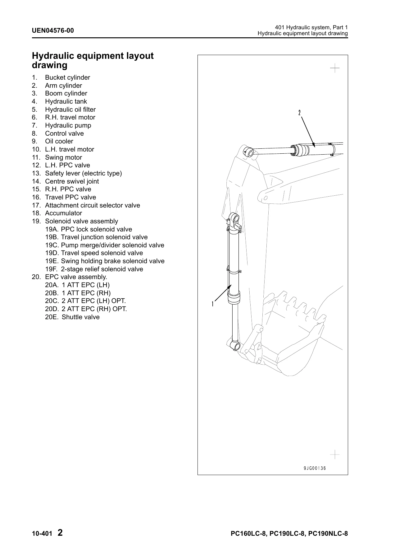
This is the heart of the manual and spans engine and cooling (including the Diesel Particulate Filter, its component parts, system description and regeneration), the power train (swing circle, swing machinery, final drive, sprocket), the undercarriage and frame (track frame, recoil spring, idler, carrier roller, track roller, track shoe), the full hydraulic system in three parts (hydraulic tank, hydraulic pump with LS and PC valves and EPC valve, control valve, valve control, PPC valve, ATT EPC valve assembly, solenoid valve, accumulator, return oil filter, centre swivel joint, travel motor, swing motor, attachment circuit selector valve, quick coupler control valve and hydraulic cylinders), work equipment, cab air conditioner piping, the electrical system (engine control, electronic control, monitor system, sensors, PPC levers and the KOMTRAX system) and the Auto Grease system.
20 Standard Value Table
The standard service value tables list the engine and chassis related standard values for new machines together with the judgement criteria used for testing, adjusting and troubleshooting. These tables are the reference used throughout the testing and troubleshooting chapters.
30 Testing and Adjusting
Broken into three parts. Part 1 covers the testing and adjusting tools, measuring engine speed, intake air pressure, exhaust gas colour, valve clearance, compression pressure, blow-by pressure and engine oil pressure; fuel system handling, pressure, discharge, return and leakage; air conditioner and fan belts; swing circle bearing clearance and track shoe tension; oil pressure in the work equipment, swing and travel circuits plus control, PC and LS circuits; solenoid valve and PPC valve output pressures; hydraulic drift locations; travel deviation adjustment; residual pressure release and oil leakage measurement. Part 2 explains the special functions of the machine monitor. Part 3 covers the engine controller voltage circuit, preparation for electrical troubleshooting, diode testing and Pm-clinic service.
40 Troubleshooting
The troubleshooting section is split into failure code tables and fuse locations; general troubleshooting information; four parts of troubleshooting by failure code; then electrical system troubleshooting (E-mode), hydraulic and mechanical system troubleshooting (H-mode), engine troubleshooting (S-mode) and Auto Grease system troubleshooting. Each entry lists the failure code, the trouble, the machine monitor or controller action, the symptom that appears on the machine, the related information and the possible causes with standard values in the normal state.
50 Disassembly and Assembly
General information on disassembly and assembly, the coating materials list, the special tool list and sketches of special tools, followed by the disassembly and assembly procedures for the engine and cooling system, power train, undercarriage and frame, hydraulic system, work equipment, cab and its attachments and the electrical system. Each procedure gives the removal sequence, the installation sequence, the coating materials and the tightening torque values.
90 Diagrams and Drawings
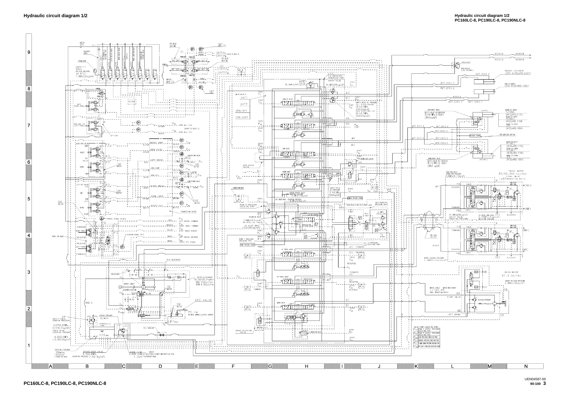
Closes with the hydraulic circuit diagram in two halves and the full electrical circuit diagram in five parts, plus the connectors table and arrangement drawing for the PC160LC-8, PC190LC-8 and PC190NLC-8. These diagrams are the reference used to trace circuits during fault finding.
Why this Komatsu Shop Manual matters
Repairing a hydraulic excavator without the correct procedures, torque values, service limits and circuit diagrams is how small faults turn into expensive downtime. This Komatsu PC160LC-8 PC190LC-8 PC190NLC-8 Shop Manual gives you the exact maintenance standards, testing and adjusting methods, failure-code diagnostics and disassembly/assembly sequences that let you diagnose a fault on the CLSS hydraulic circuit, set the LS differential pressure, re-time a swing motor, reseal a hydraulic cylinder or rebuild a final drive correctly the first time. It supports routine servicing, safety-critical adjustments, component overhauls, electrical fault finding on the CAN and monitoring network and full machine teardown.
IMAGES PREVIEW
The manual is supplied as an instant-download PDF after payment — no shipping, no waiting for a disc. Read it on a laptop, tablet or phone in the workshop, print only the pages you need for the job in front of you and keep the complete Komatsu PC160LC-8, PC190LC-8 and PC190NLC-8 Hydraulic Excavator Shop Manual at your fingertips whenever the machine is in for repair.
Reviews
There are no reviews yet.