
Massey Ferguson 6400 Electrical Equipment Workshop Manual – PDF Download
Original price was: $34.95.$21.95Current price is: $21.95.
Complete Chapter 10 Electrical Equipment workshop manual for Massey Ferguson 6400 tractors covering fuse boxes, cab and engine wiring diagrams, lighting circuits and electronic box power supply for Dynashift and Dyna-6 models.
Description
Massey Ferguson 6400 Electrical Equipment Workshop Manual
This is the complete Chapter 10 Electrical Equipment from the Massey Ferguson 6400 workshop manual, delivered as an instant-download PDF. It covers the electrical architecture of the 6400 series tractor across Europe and North America configurations, including the fuse box layouts, full cab and engine harness schematics, the lighting circuits, and the power supply routing for the electronic control boxes. Whether you are tracing a fault in the fuse box, rebuilding a damaged harness, or confirming wire colours and connector pin-outs before splicing, this Massey Ferguson 6400 electrical workshop manual gives you the diagrams and fuse/relay schedules you need to work accurately.
File Details
- Manual type: Workshop Manual – Chapter 10 Electrical Equipment
- Brand: Massey Ferguson
- Model: 6400 series
- Language: English
- File format: PDF
- Publication reference: Issue 4.a / 4.b
- Chapter sections: 10A10, 10B10, 10B11, 10B12, 10B13
Chapters Covered
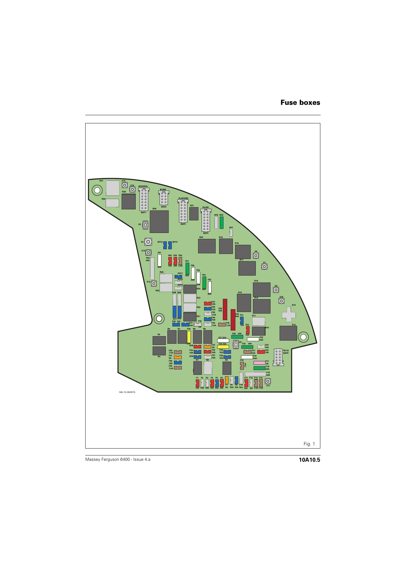
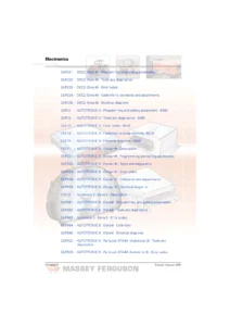
- 10A10 – Fuse boxes
- General fuse box naming and function (F, SH, R)
- Fuse amperage, size and colour table
- Version for Europe – Dynashift and Dyna-6 with Perkins engine
- Version for North America – Dynashift and Dyna-6 with Perkins engine
- Fuse and relay protected function tables
- Fuse box layout drawings
- 10B10 – Electrical diagrams: Cab equipment
- Wire colour coding: N Black, M Brown, R Red, B White, J Yellow, V Green
- Power supply types: +12V Battery permanent, +12V APC ignition key ON, +12V ACC accessories
- 31-way Deutsch connectors ENG1, ENG2, L14, CAB50, LIG1
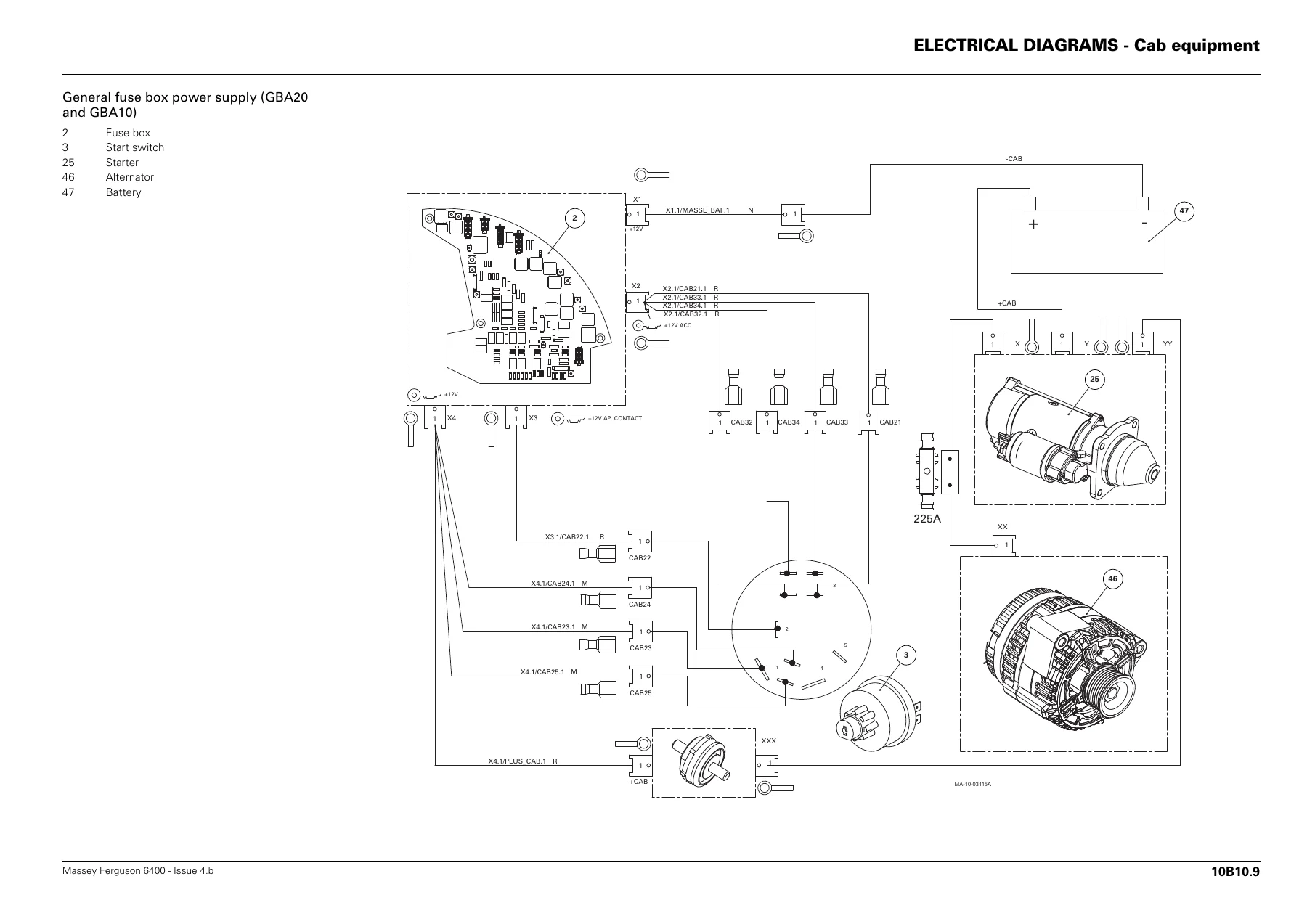
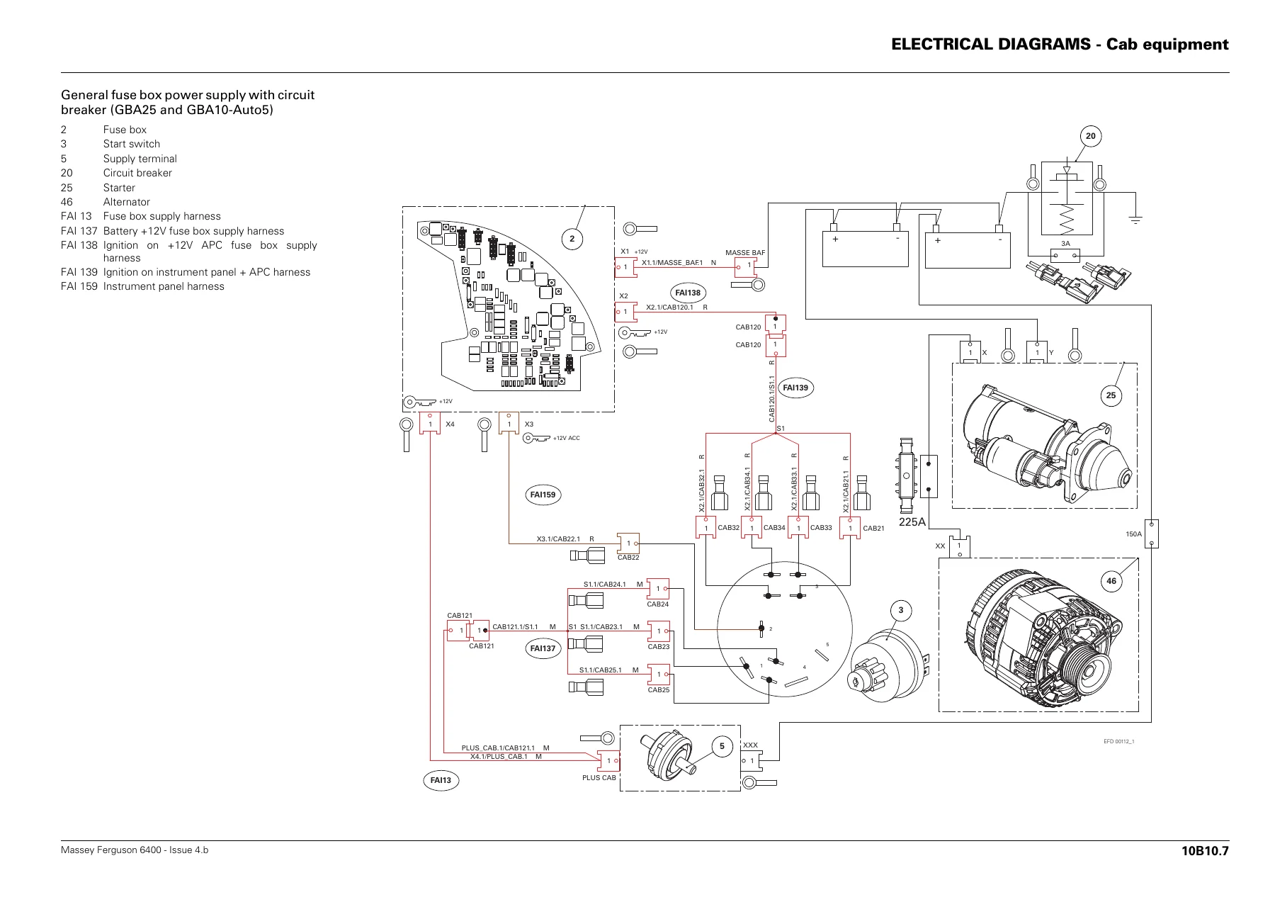
- General fuse box power supply
- Power socket connection (cigarette lighter socket)
- Cab interior power socket and SAE power socket
- Horn circuit
- Front windscreen wiper and washer pump
- Rear windscreen wiper
- Cab suspension
- Pneumatic seat adjustment control
- Radio and speaker wiring
- Manual and automatic air conditioning circuits
- Electric rear view mirror adjustment and defroster
- Door switch and roof light
- Instrument panel (DCC2) connections
- Autotronic 3 and Autotronic 5 transmission controllers
- Electronic linkage controller (ELC)
- Datatronic 2 and Datatronic 3
- Fieldstar terminal harness
- Front PTO switch and solenoid
- Handbrake switch and radar
- 16-pin diagnostics connector
- 10B11 – Electrical diagrams: Engine equipment
- Air filter vacuum sensor
- Engine oil pressure sensor – four-cylinder Perkins with mechanical injection
- Preheater relay and glow plugs
- Electronic injection harness junction (ENG4)
- Thermostart
- Fuel preheater
- Fuel gauge
- Coolant temperature sensor and switch
- Booster pump
- Injection pump solenoid valve
- Start relay, safety switch, starter and alternator
- Grid heater relay (SisuDiesel EEM)
- 10B12 – Electrical diagrams: Lighting
- Types of bulbs – Europe, North America and high-visibility model
- Trailer connector plug Europe (7-pin) with function and wire colour table
- Trailer connector plug North America
- Instrument panel lighting
- Console lighting – standard and high-visibility roof
- Main beams and dipped lights – Europe, North America and Germany
- Side lights – Europe, North America and high-visibility roof
- Number plate lighting – standard and high-visibility roof
- Stop lights and reversing light
- Roof indicators and warning lights – Europe and North America, before and after serial N145024/N145025
- Fender extension indicators
- Rotating beacons
- Footplate lighting – Europe and North America
- Work headlights power supply module and work headlights module with/without circuit breaker
- Work headlights on roof, fenders, guard rails and footplates – including Xenon variants
- 10B13 – Electrical diagrams: Supply of electronic boxes
- Autotronic 3 power supply
- Autotronic 5 Parklock and transmission No.1 / No.2 controllers
- Electronic linkage controller (ELC)
- Instrument panel (DCC2) supply
- Dana suspended front axle Autotronic 5 controller
- Perkins EEM and SisuDiesel EEM engine ECU junctions
- Datatronic 2 and Datatronic 3 supply
Across roughly 180 pages of diagrams and tables, this chapter documents the entire electrical system of the Massey Ferguson 6400 series in a way that is directly usable in the workshop. The fuse box section is not just a picture of fuses – each fuse and relay is listed with its amperage and the exact circuits it protects, split into European and North American specifications. The cab, engine, lighting and electronic box sections each carry their own connector views, splice references and wire colour coding so that any circuit in the tractor can be traced from the fuse box out to the last component. Because the schematics carry connector pin numbers alongside harness splice IDs (for example CAB3.7/CAB28.1 N), you can follow a single wire through multiple harness junctions – cab, pillar, roof, transmission, linkage and lighting – without guessing.
What This Electrical Equipment Chapter Lets You Do
The electrical system on a Massey Ferguson 6400 is spread across several harness families: the cab, pillar, roof, engine, transmission, linkage and lighting harnesses all plug into the fuse box and into each other through 31-way Deutsch connectors. When something stops working – a work light, a windscreen wiper, a brake switch, a stop light, the PTO solenoid, the air conditioning clutch, an indicator on a fender extension, or a fault stored in the Autotronic transmission or Datatronic monitor – the fast route to a fix is a diagram that shows exactly which fuse feeds it, which relay switches it and which connector pin the wire travels through. That is precisely what this manual provides, and it is why a proper Massey Ferguson 6400 electrical workshop manual is more useful on a fault-finding job than any generic wiring book.
The fuse tables in section 10A10 alone are worth having. For the European Dynashift and Dyna-6 with Perkins engine, every fuse is listed from F1 through F61 plus the shunts SH2 to SH14 and the relays R1 to R29, together with the function each one protects – from the stop lights, brake switch and horn through to the ECU supplies, front PTO, cab suspension, air conditioning compressor, radio, cigarette lighter and hazard warning lights. The North American version follows the same format with its own fuse numbering, including the roof direction indicators, fender extension direction indicators and the different headlight shunt arrangement. When a fuse blows repeatedly, knowing which functions sit on that fuse turns a blind hunt into a targeted inspection.
The lighting section (10B12) is equally practical. It documents every bulb type used on the tractor in Europe, North America and the high-visibility roof model, and then gives circuit diagrams by lighting function: main beam and dipped, side lights, number plate, stop, reversing, indicators, rotating beacons, footplate and all the work headlight configurations including the Xenon work headlights. The trailer connector pin-out is also included for both the European and North American plugs, with the function, wire code and wire colour for each pin – useful when a trailer light fault turns out to be a tractor-side connector issue.
For the electronic side, the 10B13 section covers the power supply to every electronic box on the tractor: Autotronic 3, Autotronic 5 Parklock and transmission controllers, the electronic linkage controller, the DCC2 instrument panel, the Dana suspended front axle Autotronic 5 controller, Datatronic 2 and 3, and the Perkins/SisuDiesel engine ECU junction. Each is shown with its connector pin allocation, its fuse protection and its supply and earth points, so intermittent electronic faults can be narrowed down to a supply problem, an earth problem or a genuine controller fault.
IMAGES PREVIEW
All of this is delivered as an instant-download PDF. There is no shipping, no waiting for a disc, and no risk of a used paper copy missing pages – the file can be opened on any device, searched with your PDF reader’s find function, and printed page-for-page so a clean copy can sit on the bench while you work. If you maintain, repair or restore a Massey Ferguson 6400 and you want the electrical diagrams and fuse data for the tractor in front of you, this is the chapter you need.

Reviews
There are no reviews yet.