
New Holland D180 Tier 3 Crawler Dozer Service Manual – Workshop Repair PDF
Original price was: $59.95.$39.95Current price is: $39.95.
Complete workshop service manual for New Holland D180 Tier 3 crawler dozer. Covers engine, transmission, final drives, brakes, steering differential, undercarriage, dozing equipment hydraulics, electrical system and air conditioning unit. Print No. 84151290.
Description
New Holland D180 Tier 3 Crawler Dozer Workshop Manual
This is the complete workshop service manual for the New Holland D180 Tier 3 crawler dozer, covering the LT, XLT and LGP variants in both Power Steering and Steering Clutch configurations. Published under Print No. 84151290, this manual is the same reference used by professional technicians for engine overhaul, transmission repair, final drive rebuilds, hydraulic diagnostics, brake service, undercarriage maintenance and electrical troubleshooting. Every procedure is presented with step-by-step instructions, exploded views, sectional diagrams, pressure test points, tightening torques and specification tables.
File Details
- Manual type: Workshop / Service Manual
- Brand: New Holland
- Model: D180 Tier 3 Crawler Dozer
- Variants covered: D180 LT (Power Steering), D180 XLT (Power Steering), D180 LGP (Power Steering), D180 LT (Clutch), D180 XLT (Clutch)
- Language: English
- Page count: 529
- File format: PDF
- Publication number: 84151290
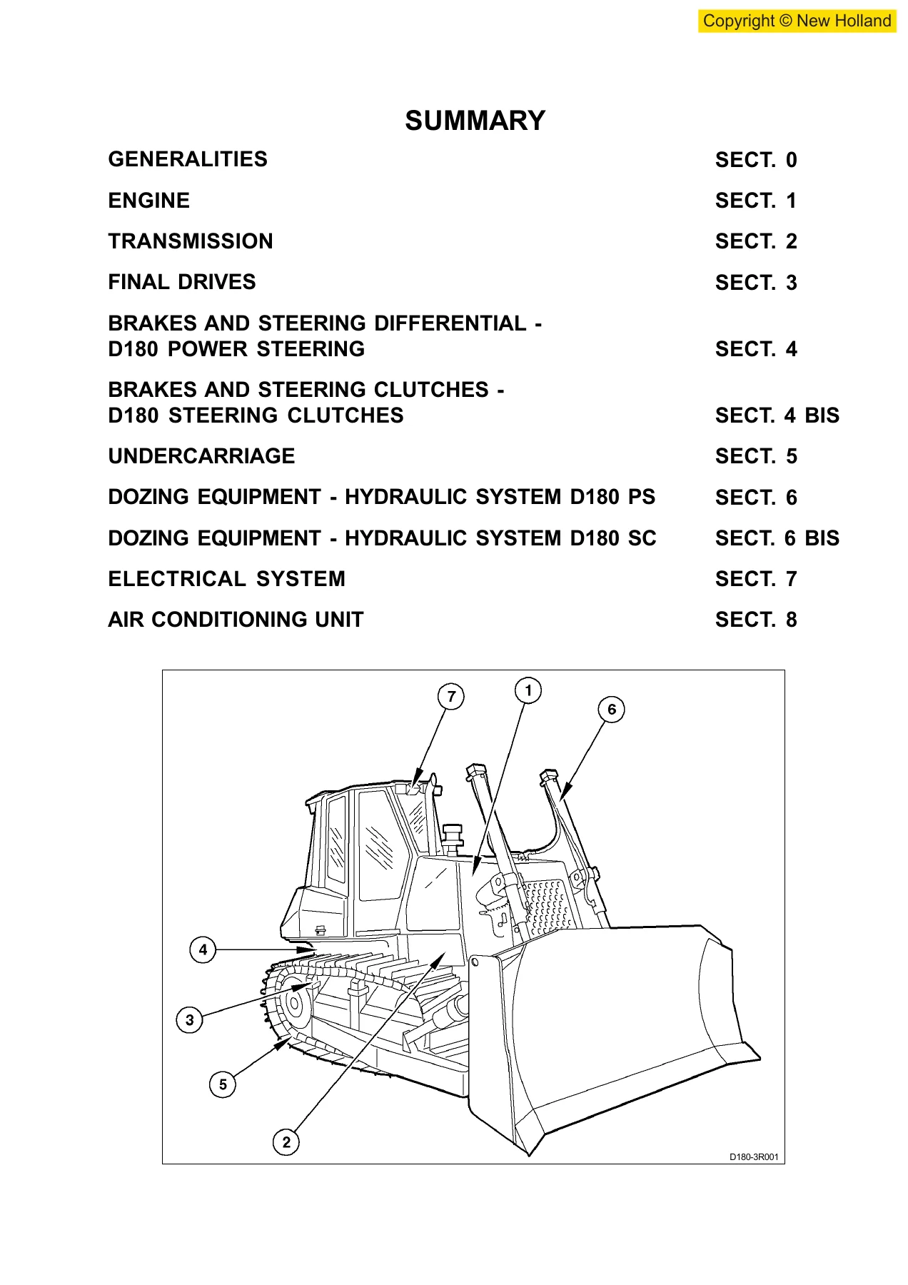
Chapters Covered
- Section 0 — Generalities
- Section 1 — Engine
- Section 2 — Transmission
- Section 3 — Final Drives
- Section 4 — Brakes and Steering Differential (D180 Power Steering)
- Section 4 BIS — Brakes and Steering Clutches (D180 Steering Clutches)
- Section 5 — Undercarriage
- Section 6 — Dozing Equipment Hydraulic System (D180 PS)
- Section 6 BIS — Dozing Equipment Hydraulic System (D180 SC)
- Section 7 — Electrical System
- Section 8 — Air Conditioning Unit
Section 0 — Generalities
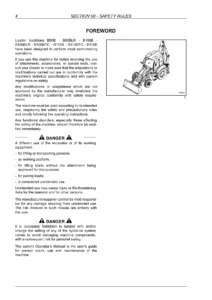
Safety rules, identification data, engine and machine data plates, marking and serial number locations, fluid capacities table, dimensions for D180 BD and PAT, technical data for D180 PS and D180 SC, weight and equipment tables, centre of gravity table, general instructions for seal installation, O-ring fitting, cleaning, disassembly and reassembly of groups, high-pressure pipe and hose routing, troubleshooting methodology, units of measure, and the complete table of tightening torques.
Section 1 — Engine
General specifications for the IVECO Series C engine, identification data, engine data tables, diagrams of engine components from left, right, rear, front and top views, engine mounting on frame, engine/converter removal and installation, radiator group removal and reinstallation, silencer group removal and reinstallation, converter group removal and reinstallation, and blink code diagnostics with error code tables for the engine ECU.
Section 2 — Transmission
Transmission torque converter hydraulic diagram, transmission housing, propeller shaft and torque converter layout, troubleshooting, torque converter stall test, delivery pressure test procedure, transmission gearshifting electric control valve, repair procedures for the torque converter including removal, reinstallation, disassembly and reassembly, transmission repair procedures including removal, reinstallation, disassembly, overhaul of forward, 3rd and reverse speed clutches, modulating valves, pressure relief valve, specifications and data, tightening torques and special tools.
Section 3 — Final Drives
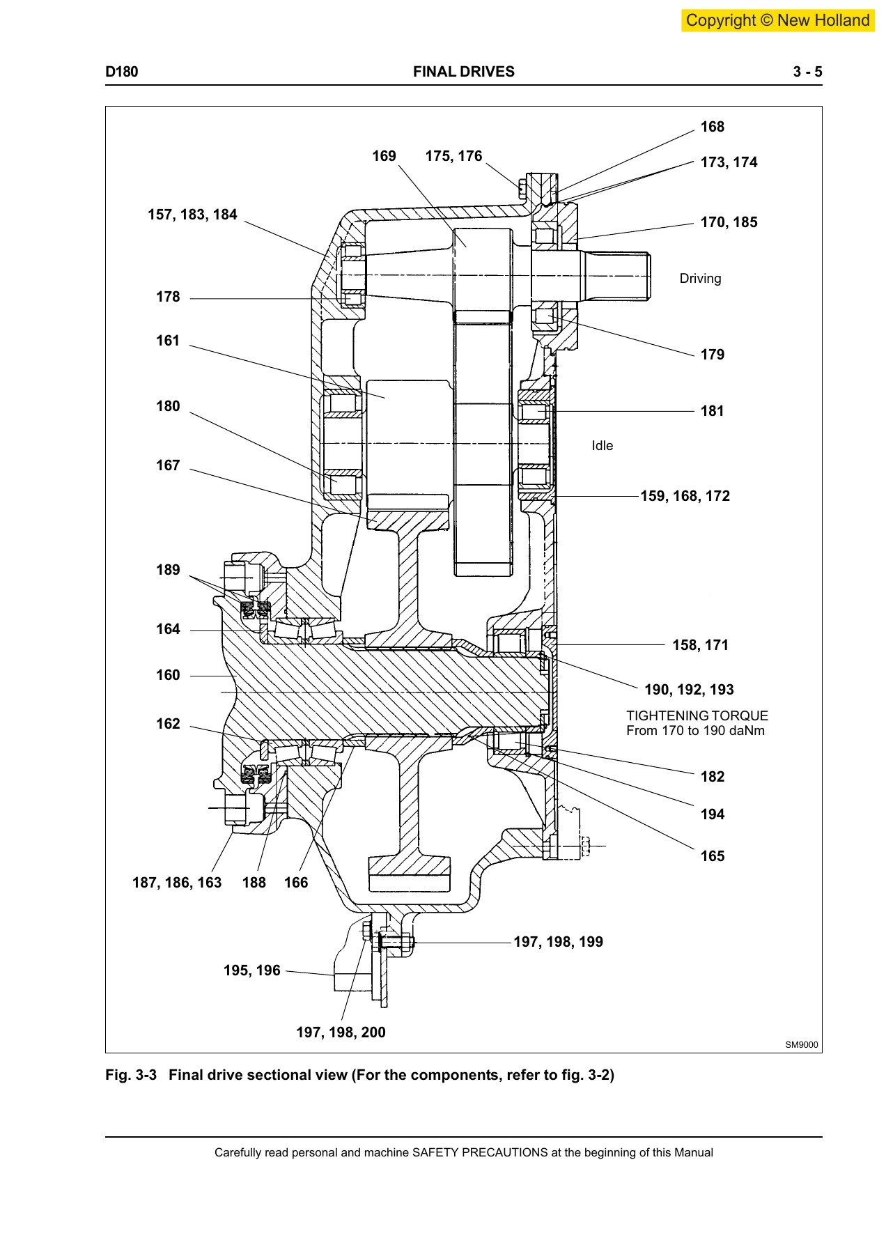
General description of the double reduction final drive with straight spur gears, final drive exploded view, sectional view, removal and disassembly procedures, pulling the housing cover, driven gear bearing removal, driving gear shaft bearing removal, installation of front seals (long life), final drive assembly, specifications and data for shaft and bearing fittings, and special tools.
Section 4 — Brakes and Steering Differential (D180 Power Steering)
Brakes hydraulic diagram, brake circuit main components including brake powering pump, brake powering valve block, brake pedal valve and brake oil filter, steering circuit main components including hydraulic motor, troubleshooting, diagnosis on display, tests including circuit pressure tests, positioning of diagnostic hoses, brake pedal adjustment, test and setting of brake powering valve block, calibration of steering levers, repair procedures for brake pedal valve, brake power pump, brakes and steering differential, bevel gear set, procedures for setting bevel pinion bearing pre-load and bevel gear crown, check of steering/equipment pump pressure, reinstallation of housing cover, specifications and data, and special tools.
Section 4 BIS — Brakes and Steering Clutches (D180 Steering Clutches)
General description of the brakes and steering clutches circuit, hydraulic diagram, main components including feeding pump, feeding valve block, proportional solenoid valves block, brake and clutch control valve, brake pedal valve, oil filters, rear transmission views, troubleshooting, diagnosis on display, pressure test of the brakes and steering clutches circuit, brake pedal adjustment, brake system pressure test, feeding valve test and setting, calibration of brakes/steering clutch levers, repair procedures for brake pedal valve, steering clutch and brake control feeding pump, brakes and steering clutches removal and disassembly of packs, bevel gear unit removal and disassembly, bevel gear re-assembly and installation, procedures for setting pinion bearing pre-load and bevel gear unit, specifications and data, and special tools.
Section 5 — Undercarriage
General description, main components including track frames, bottom rollers, support rollers, track tensioner device, idler wheels, track chains and sprocket segments, troubleshooting, inspection and adjustment of track chains, setting of track tensioner pressure relief valve, repair procedures for track chain removal and installation, replacing a damaged link, idler removal and overhaul, track chain support rollers, track chain bottom rollers, track chain tensioner spring, specifications and data for idler, sprockets, track chains, bottom rollers, support rollers, track tensioner device, front cross-member pivots, wear limits, and special tools.
Section 6 — Dozing Equipment Hydraulic System (D180 Power Steering)
General description of the hydraulic system operation, equipment hydraulic schematic for PAT and bulldozer configurations, blade hydraulic tilt, blade control lever positions, ripper control lever positions, tests including troubleshooting using test equipment, use of the electronic service tool, procedure for the dual setting relief valve, repair procedures for hydraulic oil reservoir, equipment hydraulic pump, hydraulic control valve, blade, ripper, specifications and data for electro/hydraulic control valve, hydraulic power pump, blade lifting cylinder ball joint, blade lifting control cylinder, blade tilt control cylinder (bulldozer and angledozer versions), ripper cylinder PD 180, ripper cylinder RP 14F, blade push arms and rods, frame and rods, ripper linkage for LT/XLT and LGP models, thrust arch and PAT blade, blade angle cylinder (PAT version), blade tilt cylinder (PAT version), and special tools.
Section 6 BIS — Dozing Equipment Hydraulic System (D180 Steering Clutches)
General description of the hydraulic system operation, diagram of dozing equipment hydraulic system, troubleshooting, tests including use of the electronic service tool, repair procedures for hydraulic oil reservoir, equipment hydraulic pump, blade installation, hydraulic control valve, specifications and data for hydraulic control valve, supply hydraulic pump, blade lifting cylinder ball joint, blade lifting control cylinder, blade tilt control cylinder (bulldozer and angledozer versions), ripper cylinder, blade push arms and rods, frame and rods, ripper linkage for LT/XLT model, and special tools.
Section 7 — Electrical System
Safety rules, electrical diagram of protections tree, fuses for CAB and ROPS versions, link fuses and cold starting fuse, main switch, engine starting switch, back-up alarm, starter motor, alternator, manual accelerator control potentiometer, washer tank motors, cab wiper motors, implement/drivetrain safety lever, instrument panel and monitor operation, electrical diagram of instrument panel/monitor, monitor senders for air cleaner clogging, engine coolant max temperature, engine RPM, engine oil low pressure, alternator, fuel level, hydraulic oil filter clogging, brakes and steering clutches oil low pressure, transmission oil low pressure, transmission oil max temperature, display and diagnosis on display, buzzer, relays and diodes, main connectors 19-21-23 ways, and blade control pilot valve wiring.
Section 8 — Air Conditioning Unit
Operating instructions, technical data, cab climate conditioner, service precautions, tool connections, discharging, refrigerant charging, leak inspection, special tools, and troubleshooting charts covering fan motor, insufficient air flow, insufficient cooling, compressor operation, gauge pressure diagnosis and refrigerant circulation issues.
What This Manual Enables You To Do
With this New Holland D180 Tier 3 service manual, you can perform complete engine overhauls on the IVECO 667TA-6.7 diesel, rebuild the Twin Disc torque converter, disassemble and reassemble the full power shift transmission with its five clutches, service the double reduction final drives, repair the brakes and steering differential or steering clutch packs, rebuild the undercarriage including track tensioner springs and rollers, troubleshoot the load sensing hydraulic system for both dozing equipment and steering, diagnose electrical faults using blink codes and the monitor display, and service the air conditioning system. Every procedure includes the manufacturer’s specified tolerances, pressure settings, tightening torques and wear limits, so you can work to the correct specifications rather than guessing.
Whether you are a professional technician maintaining a fleet of D180 dozers, a farmer or contractor keeping a single machine running, or a mechanic performing a major repair, this workshop manual gives you the same information the dealer service department uses. The sectional views and exploded diagrams make complex assemblies understandable, the pressure test points and diagnostic tables speed up troubleshooting, and the torque tables ensure every fastener is tightened correctly.
IMAGES PREVIEW
Instant PDF Delivery
This New Holland D180 Tier 3 crawler dozer service manual is delivered as an instant PDF download after payment. No shipping, no waiting for a physical book. You can view it on any computer, tablet or smartphone, print individual pages or entire sections for use in the workshop, and search across the full document to find the specification or procedure you need. The PDF format keeps all diagrams, tables and illustrations exactly as published, so you always have a clean, readable reference at your fingertips.
Reviews
There are no reviews yet.