★ TRUSTED BY 321,897+ PROFESSIONALS WORLDWIDE
🏒
Trusted Business
Verified & Licensed
πŸ›‘οΈ
Virus Free Files
100% Safe Downloads
πŸ”’
Secure Payment
SSL Protected
⚑
Instant Delivery
Available Immediately
Sale!

Piper PA-34-200T Seneca II Illustrated Parts Catalog 1975-1981 – 761-589 PDF

Original price was: $39.95.Current price is: $24.95.

Complete illustrated parts catalog for the Piper PA-34-200T Seneca II, covering 1975 through 1981 models. Document 761-589 with exploded views, part numbers, and serial number applicability across all eleven sections.

⚑
Instant PDF Download
Available immediately
πŸ’Ύ
Save to Your Device
Download & keep forever
πŸ›‘οΈ
Antivirus Scanned
100% virus-free
🌍
Trusted Worldwide
175,000+ customers

Description

Piper PA-34-200T Seneca II Parts Catalog – Document 761-589

This Piper PA-34-200T Seneca II Parts Catalog (document number 761-589) is the complete illustrated parts breakdown for the Seneca II, covering every major assembly from wing to tail cone. Published by Piper Aircraft Corporation and revised through December 2009, this catalog spans serial numbers from the first 1975 models through the 1981 production run. Every part listing includes figure and index numbers, Piper part numbers, nomenclature, quantity required, and the specific serial numbers affected.

File Details

  • Manual Type: Illustrated Parts Catalog
  • Brand: Piper Aircraft Corporation
  • Model: PA-34-200T Seneca II
  • Document Number: 761-589 (761 589)
  • Models Covered: 1975 through 1981 PA-34-200T Seneca II
  • Serial Number Ranges: 34-7570002 to 34-8170092 (see full breakdown below)
  • Language: English
  • Page Count: Approximately 460 pages
  • File Format: PDF

Serial Number Coverage

The catalog covers the following PA-34-200T Seneca II serial number ranges:

  • 1975 Models: 34-7570002 to 34-7570327 inclusive
  • 1976 Models: 34-7670001 to 34-7670371 inclusive
  • 1977 Models: 34-7770001 to 34-7770441 inclusive
  • 1978 Models: 34-7870001 to 34-7870474 inclusive
  • 1979 Models: 34-7970001 to 34-7970530 inclusive
  • 1980 Models: 34-8070001 to 34-8070367 inclusive
  • 1981 Models: 34-8170001 to 34-8170092 inclusive

Chapters Covered

The catalog is divided into eleven major sections, each with its own illustration and parts listing:

Complete PDF Bookmark Tree

Complete Bookmarks

The complete bookmarks in the β€œPiper PA-34-200T Seneca II Illustrated Parts Catalog 1975-1981 – 761-589 PDF” are as follows:

761-589 – SENECA II PARTS CATALOG – PA-34-200Tp. 1
REVISION STATUSp. 2
INTRODUCTIONp. 3
HOW TO IDENTIFY A PART IF YOU KNOW WHAT IT LOOKS LIKE AND KNOW WHERE IT IS LOCATEDp. 4
HOW TO ORDER PARTSp. 4
GENERAL INFORMATIONp. 4
PA-34-200T SERIAL NUMBER INFORMATIONp. 5
SERIAL NUMBER EXPLANATIONp. 5
STANDARD PAINT CHARTp. 6
TABLE OF CONTENTSp. 8
FIGURE 1. COMPLETE AIRPLANEp. 11
SECTION I – WING GROUPp. 12
FIGURE 2. WING INSTALLATIONp. 12
FIGURE 3. WING LEADING EDGE ASSEMBLYp. 18
FIGURE 4. WING TRAILING EDGE ASSEMBLYp. 23
FIGURE 5. AILERON ASSEMBLYp. 28
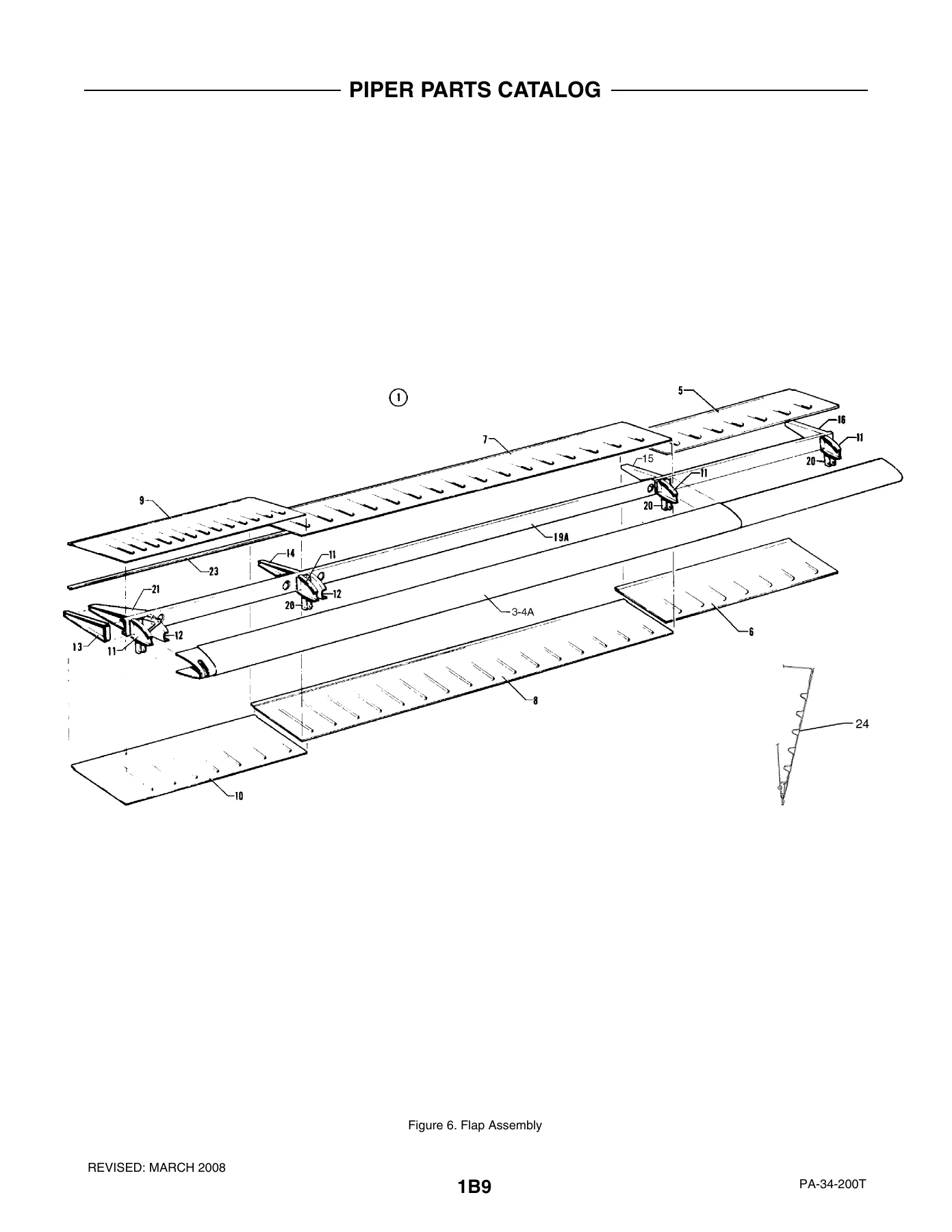
FIGURE 6. FLAP ASSEMBLYp. 31
SECTION II – FUSELAGE GROUPp. 34
FIGURE 7. FUSELAGE ASSEMBLY – COMPLETEp. 34
FIGURE 8. FUSELAGE NOSE CONE ASSEMBLYp. 38
FIGURE 9. FUSELAGE UPPER FORWARD COCKPIT ASSEMBLYp. 41
FIGURE 10. FUSELAGE UPPER CENTER COCKPIT ASSEMBLYp. 46
FIGURE 11. FUSELAGE UPPER AFT COCKPIT ASSEMBLYp. 51
FIGURE 12. FUSELAGE LOWER FORWARD COCKPIT ASSEMBLYp. 54
FIGURE 13. FUSELAGE LOWER AFT COCKPIT ASSEMBLYp. 59
FIGURE 14. FUSELAGE AFT SECTIONp. 63
FIGURE 15. FUSELAGE ENCLOSURE INSTALLATIONp. 68
FIGURE 16. FUSELAGE FORWARD CABIN DOOR (SERIAL NOS. 34-7570001 TO 34-7670063 INCL)p. 73
FIGURE 16A. FUSELAGE FORWARD CABIN DOOR (SERIAL NOS. 34-7670064 AND UP)p. 77
FIGURE 17. FUSELAGE AFT CABIN DOORp. 82
FIGURE 18. FUSELAGE AFT CARGO DOORp. 87
FIGURE 19. FUSELAGE FORWARD BAGGAGE DOOR ASSEMBLYp. 92
FIGURE 20. FORWARD BAGGAGE COMPARTMENT FINISHING INSTALLATIONp. 96
FIGURE 21. COCKPIT FINISHING INSTALLATIONp. 99
FIGURE 21A. WINDOW CURTAINS INSTALLATION (SERIAL NOS. 34-7770001 AND UP)p. 106
FIGURE 22. FORWARD FRESH AIR DUCT AND HEADLINER INSTALLATIONp. 109
FIGURE 23 . AFT FRESH AIR DUCT INSTALLATIONp. 112
FIGURE 24. CARPET INSTALLATIONp. 116
FIGURE 25. SEATS INSTALLATIONp. 125
FIGURE 26. VERTICALLY ADJUSTABLE FRONT SEAT ASSEMBLYp. 131
FIGURE 27. 7TH SEAT INSTALLATIONp. 136
FIGURE 27A. AFT FACING SEAT ASSEMBLY – CENTER (SERIAL NOS. 34-7770001 AND UP)p. 140
FIGURE 27B. CLUB SEATING INSTALLATION (SERIAL NOS. 347770001 AND UP)p. 143
FIGURE 28. INSTRUMENT PANEL INSTALLATIONp. 147
FIGURE 29. GYRO PRESSURE SYSTEM INSTALLATIONp. 152
FIGURE 30. PITOT STATIC SYSTEM INSTALLATION (SERIAL NOS. 34-7570001 TO 34-7670136 INCL)p. 156
FIGURE 30A. PITOT STATIC SYSTEM INSTALLATION (SERIAL NOS. 34-7670137 AND UP)p. 160
FIGURE 31. PNEUMATIC DEICER INSTALLATIONp. 164
FIGURE 32. HEAT AND DEFROST SYSTEM INSTALLATIONp. 168
FIGURE 33. JANITROL HEATER ASSEMBLYp. 171
FIGURE 34. JANITROL HEATER COMPONENTSp. 174
FIGURE 35. HEATER DUCT INSTALLATIONp. 177
FIGURE 36. HEATER FUEL SYSTEM INSTALLATIONp. 180
FIGURE 37. HEATER CONTROLS INSTALLATIONp. 183
FIGURE 37A. AIR CONDITIONING COMPRESSOR AND REFRIGERANT LINES INSTALLATION (SERIAL NOS. 34-7970001 AND UP)p. 187
FIGURE 37B. AIR CONDITIONING DUCT AND EVAPORATOR INSTALLATION (SERIAL NOS. 34-7970001 AND UP)p. 190
FIGURE 37C. AIR CONDITIONING CONDENSER AND SCOOP INSTALLATION (SERIAL NOS. 34-7970001 AND UP)p. 194
FIGURE 37D. OXYGEN SYSTEM INSTALLATION (FIXED) (SERIAL NOS. 34-8070001 AND UP)p. 197
SECTION III – TAIL SURFACES GROUPp. 201
FIGURE 38. TAIL SURFACES INSTALLATIONp. 201
FIGURE 39. STABILATOR ASSEMBLYp. 205
FIGURE 40. FIN ASSEMBLYp. 208
FIGURE 41. RUDDER ASSEMBLYp. 211
SECTION IV – CHASSIS GROUPp. 214
FIGURE 42. NOSE GEAR INSTALLATIONp. 214
FIGURE 43. NOSE GEAR ASSEMBLYp. 218
FIGURE 44. NOSE WHEEL ASSEMBLY (CLEVELAND)p. 222
FIGURE 44A. NOSE WHEEL ASSEMBLY (MCCAULEY)p. 225
FIGURE 45. MAIN GEAR INSTALLATIONp. 228
FIGURE 46. MAIN GEAR ASSEMBLYp. 234
FIGURE 47. MAIN WHEEL ASSEMBLYp. 238
FIGURE 48. BRAKE ASSEMBLYp. 241
FIGURE 49. NOSE AND MAIN GEAR DOOR ACTUATION INSTALLATIONSp. 244
FIGURE 50. HAND BRAKE INSTALLATIONp. 248
FIGURE 51. TOE BRAKE INSTALLATIONp. 252
FIGURE 52. TOE BRAKE MASTER CYLINDER ASSEMBLYp. 255
SECTION V – HYDRAULIC SYSTEM GROUPp. 258
FIGURE 53. HYDRAULIC SYSTEM INSTALLATION (SERIAL NOS. 34-7570001 TO 34-7970104 INCL)p. 258
FIGURE 53A. HYDRAULIC SYSTEM INSTALLATION (SERIAL NOS. 34-7970105 AND UP)p. 262
SECTION VI – POWER PLANT GROUPp. 267
FIGURE 54. POWER PLANT INSTALLATIONp. 267
FIGURE 54A. TWO BLADE PROPELLER ASSEMBLY (HARTZELL)p. 271
FIGURE 54B. THREE BLADE PROPELLER ASSEMBLY (MCCAULEY) (SERIAL NOS. 34-7970001 AND UP)p. 275
FIGURE 54C. PROPELLER SYNCHROPHASER SYSTEM INSTALLATIONp. 279
FIGURE 55. ENGINE BAFFLE INSTALLATIONp. 282
FIGURE 56. ENGINE COWL ASSEMBLYp. 286
FIGURE 57. COWL FLAP INSTALLATIONp. 290
FIGURE 58. ENGINE CONTROLS INSTALLATIONp. 293
FIGURE 59. QUADRANT ASSEMBLYp. 297
FIGURE 60. NACELLE INSTALLATIONp. 300
SECTION VII – FUEL SYSTEM GROUPp. 303
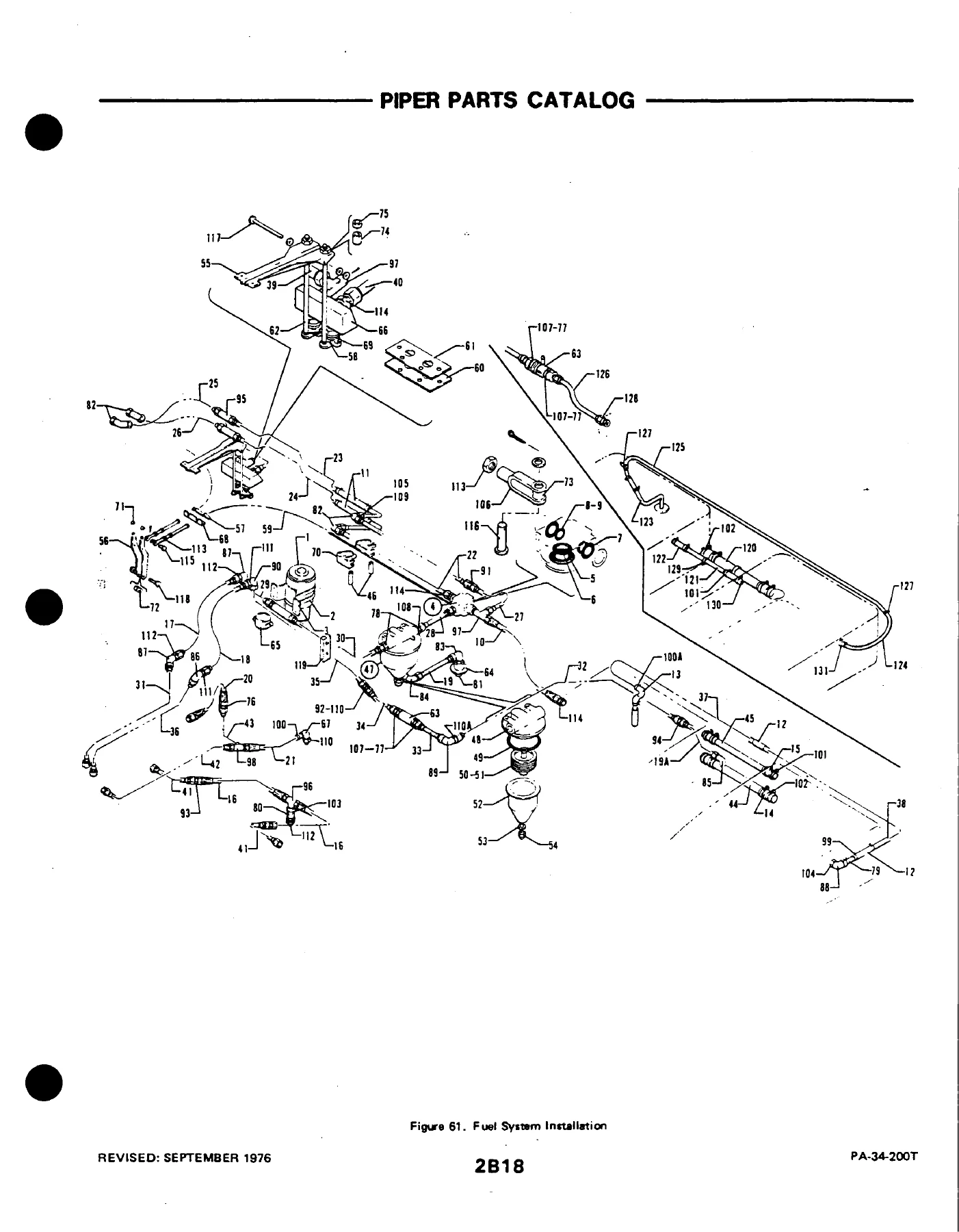
FIGURE 61. FUEL SYSTEM INSTALLATIONp. 303
FIGURE 62. ENGINE INSTRUMENT LINES INSTALLATIONp. 310
FIGURE 63. FUEL TANK ASSEMBLIESp. 314
SECTION VIII – CONTROL SYSTEM GROUPp. 318
FIGURE 64. AILERON CONTROL INSTALLATIONp. 318
FIGURE 65. RUDDER CONTROL INSTALLATIONp. 322
FIGURE 66. RUDDER TRIM INSTALLATIONp. 325
FIGURE 67. STABILATOR CONTROL INSTALLATIONp. 329
FIGURE 68. STABILATOR TRIM INSTALLATIONp. 333
FIGURE 69. FLAP CONTROL INSTALLATIONp. 337
FIGURE 70. CONTROL WHEEL INSTALLATIONp. 341
FIGURE 71. BOBWEIGHT INSTALLATIONp. 345
FIGURE 72. RUDDER PEDAL INSTALLATIONp. 348
SECTION IX – ELECTRICAL SYSTEM GROUPp. 351
FIGURE 73. ELECTRICAL SYSTEM INSTALLATIONp. 351
FIGURE 74. INSTRUMENT PANEL ELECTRICAL INSTALLATIONp. 356
FIGURE 74A. AIR CONDITIONING ELECTRICAL INSTALLATION (SERIAL NOS. 34-7970001 AND UP)p. 360
FIGURE 75. STROBE LIGHTS INSTALLATIONp. 363
FIGURE 76. EXTERNAL POWER SUPPLY INSTALLATIONp. 366
FIGURE 77. LANDING LIGHT ASSEMBLYp. 369
FIGURE 78. TWO BLADE PROPELLER ELECTRIC DEICER INSTALLATIONp. 372
FIGURE 78A. THREE BLADE PROPELLER ELECTRIC DEICER INSTALLATION (SERIAL NOS. 34-7970001 AND UP)p. 375
FIGURE 79 . HEATED GLASS PANEL INSTALLATIONp. 379
SECTION X – ELECTRONICS GROUPp. 382
FIGURE 80. ELECTRIC PITCH TRIM INSTALLATIONp. 382
FIGURE 81. AUTOCONTROL III B INSTALLATIONp. 385
FIGURE 81A. ALTIMATIC III C INSTALLATIONp. 388
FIGURE 81B. KING KFC-200 AUTOPILOT/FLIGHT DIRECTOR INSTALLATION (SERIAL NOS. 34-7970001 AND UP)p. 392
FIGURE 82. PIPER AUTOMATIC LOCATOR (ELT) INSTALLATION (GARRETT MFG LTD)p. 395
FIGURE 82A. PIPER AUTOMATIC LOCATOR (ELT) INSTALLATION (COMMUNICATIONS COMPONENTS CORP)p. 398
FIGURE 82B. PIPER AUTOMATIC LOCATOR (ELT) INSTALLATION (NARCO AVIONICS)p. 402
FIGURE 83. RADIO ANTENNA SYSTEM AND STATIC WICKS INSTALLATIONp. 405
FIGURE 84. AUDIO SELECTOR ASSEMBLYp. 409
FIGURE 84A. AVIONICS COOLING INSTALLATIONp. 412
FIGURE 85. RADAR ALTIMETER INSTALLATION (BONZER)p. 415
FIGURE 86. RADAR ALTIMETER INSTALLATION (KING) (SERIAL NOS. 34-8070001 AND UP)p. 418
FIGURE 87. RADAR SYSTEM INSTALLATION (BENDIX) (SERIAL NOS. 34-7870001 AND UP)p. 421
FIGURE 88. ENCODER INSTALLATION (NARCO- AR 500 & UNITED – 5125-P3) (SERIAL NOS. 34-7770001 AND UP)p. 425
RADIO INSTALLATION DRAWINGSp. 428
SECTION XI – MISCELLANEOUS GROUPp. 431
FIGURE 89. PLACARDS AND EXTERIOR STENCILSp. 431
OPTIONAL EQUIPMENT KITS AND REPAIR KITSp. 437
NUMERICAL INDEXp. 439

  • Section I – Wing Group: Wing Installation, Wing Leading Edge Assembly, Wing Trailing Edge Assembly, Aileron Assembly, Flap Assembly
  • Section II – Fuselage Group: Fuselage Assembly – Complete, Fuselage Nose Cone Assembly, Upper and Lower Cockpit Assemblies (Forward, Center, Aft), Fuselage Enclosure Installation, Forward Cabin Door, Aft Cabin Door, Aft Cargo Door, Baggage Door Assembly, Cockpit Finishing, Window Curtains, Fresh Air Ducts, Carpet Installation, Seats Installation, Vertically Adjustable Front Seat, 7th Seat, Aft Facing Seat, Club Seating, Instrument Panel, Gyro Pressure System, Pitot Static System, Pneumatic Deicer, Heat and Defrost System, Janitrol Heater, Heater Ducts, Heater Fuel System, Heater Controls, Air Conditioning Compressor and Refrigerant Lines, Air Conditioning Duct and Evaporator, Air Conditioning Condenser and Scoop, Oxygen System
  • Section III – Tail Surfaces: Tail Surfaces Installation, Stabilator Assembly, Fin Assembly, Rudder Assembly
  • Section IV – Chassis Group: Nose Gear Installation, Nose Gear Assembly, Nose Wheel Assembly (Cleveland and McCauley), Main Gear Installation, Main Gear Assembly, Main Wheel Assembly, Brake Assembly, Nose and Main Gear Door Actuation, Hand Brake Installation, Toe Brake Installation, Toe Brake Master Cylinder Assembly
  • Section V – Hydraulic System Group: Hydraulic System Installation (two configurations based on serial number)
  • Section VI – Power Plant Group: Power Plant Installation, Two Blade Propeller Assembly (Hartzell), Three Blade Propeller Assembly (McCauley), Propeller Synchrophaser System, Engine Baffle Installation, Engine Cowl Assembly, Cowl Flap Installation, Engine Controls Installation, Quadrant Assembly, Nacelle Installation
  • Section VII – Fuel System Group: Fuel System Installation, Engine Instrument Lines Installation, Fuel Tank Assemblies
  • Section VIII – Control System Group: Aileron Control Installation, Rudder Control Installation, Rudder Trim Installation, Stabilator Control Installation, Stabilator Trim Installation, Flap Control Installation, Control Wheel Installation, Bobweight Installation, Rudder Pedal Installation
  • Section IX – Electrical System Group: Electrical System Installation, Instrument Panel Electrical Installation, Air Conditioning Electrical Installation, Strobe Lights Installation, External Power Supply Installation, Landing Light Assembly, Two Blade Propeller Electric Deicer Installation, Three Blade Propeller Electric Deicer Installation, Heated Glass Panel Installation
  • Section X – Electronics Group: Electric Pitch Trim Installation, AutoControl III B Installation, AltiMatic III C Installation, King KFC-200 AutoPilot/Flight Director Installation, Piper Automatic Locator (ELT) Installations, Radio Antenna System and Static Wicks Installation, Audio Selector Assembly, Avionics Cooling Installation, Radar Altimeter Installation, Radar System Installation, Encoder Installation, Radio Installation Drawings
  • Section XI – Miscellaneous Group: Placards and Exterior Stencils, Optional Equipment Kits, Repair Kits, Numerical Index

What This Parts Catalog Gives You

This is not a service manual or overhaul guide. It is the parts identification reference that tells you exactly which part number goes where on a PA-34-200T Seneca II, and whether that part applies to your specific serial number. The exploded-view illustrations in each section break down every major assembly into its component parts, with index numbers that cross-reference directly to the parts listing on the facing page. For each part you get the Piper part number, the nomenclature, the quantity required, and the serial number range the part fits. That last column is critical on the Seneca II because Piper made running changes across the 1975-1981 production run, and a part that fits a 1975 model may not fit a 1981 aircraft.

When you are ordering a replacement component, rebuilding a damaged assembly, or tracking down a discrepancy between what is installed and what the book says should be there, this catalog is the reference that resolves the question. It also includes commercial hardware callouts (nuts, bolts, screws) where Piper listed them for main assemblies and installations, and it flags optional equipment items in their proper sections.

Who This Catalog Is For

IA mechanics and A&P technicians working on Seneca II airframes will find the illustrated breakdowns and serial number callouts indispensable for correct parts ordering. Owners and operators doing their own parts research can use it to confirm part numbers before contacting a distributor. Restoration shops and salvage operations working with PA-34-200T airframes get a complete map of every assembly and sub-assembly. Even if you are just trying to identify a mystery bracket or fitting, the figure and index system gets you to the right page quickly.

Why the Serial Number Column Matters

Piper built the Seneca II across seven model years, and the parts catalog reflects every change along the way. The β€œSerial Numbers Affected” column tells you at a glance whether a part applies to your aircraft. Some parts fit all serial numbers; others are specific to a narrow range. Without this catalog, you are guessing. With it, you know before you order whether a part is correct for your airframe.

Get Instant Access

IMAGES PREVIEW

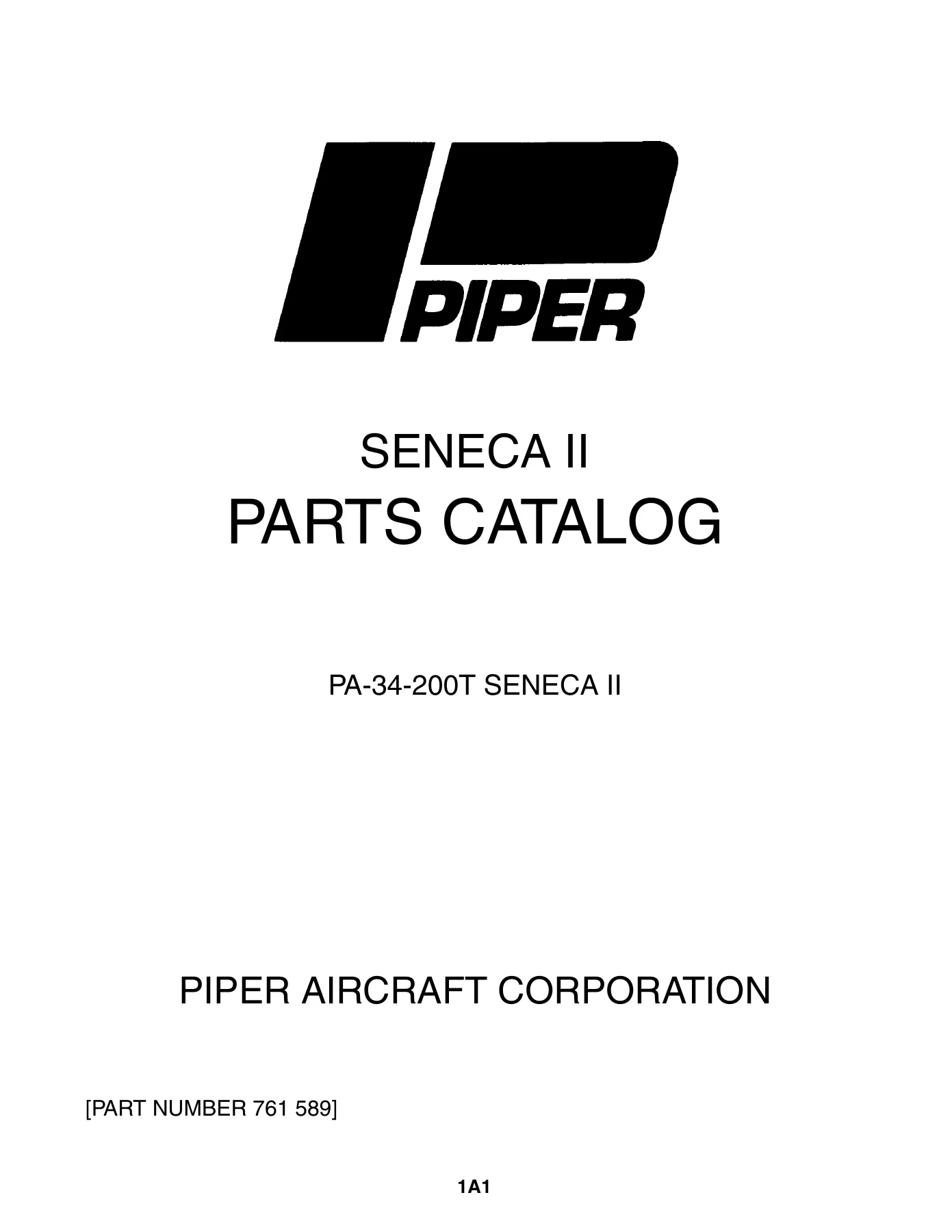
Piper PA-34-200T Seneca II Illustrated Parts Catalog 1975-1981 - 761-589 PDF β€” PDF page 1 preview
Piper PA-34-200T Seneca II Illustrated Parts Catalog 1975-1981 - 761-589 PDF β€” PDF page 31 preview
Piper PA-34-200T Seneca II Illustrated Parts Catalog 1975-1981 - 761-589 PDF β€” PDF page 303 preview

This Piper PA-34-200T Seneca II Parts Catalog (761-589) is delivered as an instant PDF download. No shipping, no waiting. The file works on any device β€” desktop, laptop, tablet, or phone β€” and you can print the pages you need for the shop or hangar. Whether you are ordering a single part or planning a full restoration, having the complete illustrated parts breakdown at your fingertips saves time, prevents wrong-part orders, and gives you the confidence that comes from working from the actual Piper documentation.

Reviews

There are no reviews yet.

Be the first to review “Piper PA-34-200T Seneca II Illustrated Parts Catalog 1975-1981 – 761-589 PDF”

What Our Customers Say

β˜…β˜…β˜…β˜…β˜… Live reviews from customers
Loading customer reviews...
0
    0
    Your Cart
    Your cart is emptyReturn to Shop
    πŸ›’
    Recently Purchased
    πŸ•’ verified order