
Piper PA-34-200T Seneca II Illustrated Parts Catalog 1975-1981 – PDF
Original price was: $39.95.$23.95Current price is: $23.95.
Complete illustrated parts catalog for the Piper PA-34-200T Seneca II, covering serial numbers 34-7570001 through 34-8170092 across the 1975-1981 model years. Includes exploded-view illustrations, Piper part numbers, nomenclature, quantities, and serial number applicability for every major airframe and systems group.
Description
Piper PA-34-200T Seneca II Illustrated Parts Catalog
This Piper PA-34-200T Seneca II Illustrated Parts Catalog is a comprehensive, illustrated parts reference for the Seneca II twin-engine aircraft, published under Piper part number 761 589 and revised through May 1983. It covers airframe serial numbers 34-7570001 through 34-8170092, spanning the 1975 through 1981 model years.
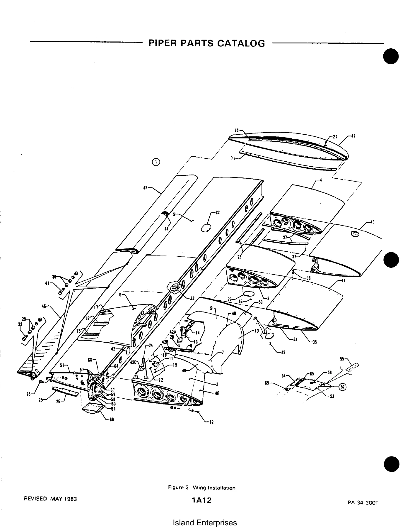
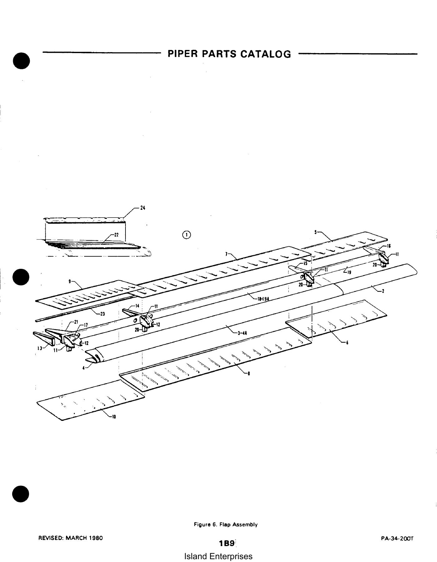
Every major section of the aircraft is broken down into exploded-view illustrations with corresponding parts listings. Each listed part carries a figure and index number, Piper part number, special-use code where applicable, nomenclature, quantity required, and the specific serial number ranges affected. That structure makes it possible to confirm whether a given part is correct for your particular Seneca II before you order.
File Details
- Manual Type: Illustrated Parts Catalog (Aerofiche format)
- Brand: Piper Aircraft Corporation
- Model: PA-34-200T Seneca II
- Document Number: 761 589
- Original Issue Date: August 12, 1974
- Latest Revision: May 1983
- Language: English
- File Format: PDF
- Page Count: Approximately 470 pages
Chapters Covered
The catalog is divided into eleven major sections, each containing its own illustrations and parts listing:
- Section I — Wing Group: Wing installation, leading edge assembly, trailing edge assembly, aileron assembly, and flap assembly
- Section II — Fuselage Group: Complete fuselage assembly, nose cone, upper and lower cockpit sections, aft fuselage, enclosure installation, forward cabin door, aft cabin door, cargo door, forward baggage door, baggage compartment finishing, cockpit finishing, window curtains, fresh air ducts and headliner, carpet, seats, vertically adjustable front seats, 7th seat installation, aft facing seat, club seating, instrument panel, gyro pressure system, pitot static system, pneumatic deicer, heat and defrost system, Janitrol heaters, heater duct, heater fuel system, heater controls, air conditioning compressor and refrigerant lines, air conditioning duct and evaporator, air conditioning condenser and scoop, and fixed oxygen system
- Section III — Tail Surfaces Group: Tail surfaces installation, stabilator assembly, fin assembly, and rudder assembly
- Section IV — Chassis Group: Nose gear installation, nose gear assembly, nose wheel assembly (Cleveland and McCauley), main gear installation, main gear assembly, main wheel assembly, brake assembly, nose and main gear door actuation, hand brake installation, toe brake installation, and toe brake master cylinder assembly
- Section V — Hydraulic System Group: Hydraulic system installation for early and late serial number ranges
- Section VI — Power Plant Group: Power plant installation, two-blade Hartzell propeller assembly, three-blade McCauley propeller assembly, propeller synchrophaser system, engine baffle installation, engine cowl assembly, cowl flap installation, engine controls installation, quadrant assembly, and nacelle installation
- Section VII — Fuel System Group: Fuel system installation, engine instrument lines installation, and fuel tank assemblies
- Section VIII — Control System Group: Aileron control installation, rudder control installation, rudder trim installation, stabilator control installation, stabilator trim installation, flap control installation, control wheel installation, bobweight installation, and rudder pedal installation
- Section IX — Electrical System Group: Electrical system installation, instrument panel electrical installation, air conditioning electrical installation, strobe lights installation, external power supply installation, landing light assembly, two-blade propeller electric deicer installation, three-blade propeller electric deicer installation, and heated glass panel installation
- Section X — Electronics Group: Electric pitch trim installation, AutoControl III B installation, AltiMatic III C installation, King KFC-200 AutoPilot/Flight Director installation, Piper Automatic Locator (ELT) installations for Garrett, Communications Components Corp, and Narco Avionics, radio antenna system and static wicks installation, audio selector assembly, avionics cooling installation, radar altimeter installations, radar system installation, and encoder installation
- Section XI — Miscellaneous Group: Placards and exterior stencils, optional equipment kits, repair kits, and numerical index
Each illustrated figure is followed by a parts listing that provides the figure and index number, part number, code letter, nomenclature, number required, and serial number applicability. The parts listings use an indentation system to show assembly relationships — unindented items are main assemblies that include the indented components below them. Code letters in the listings indicate special ordering conditions, such as parts that must be purchased from a specific Piper facility.
The catalog also includes a numerical index at the rear, allowing you to locate any part number quickly and find its associated figure and index number.
What This Seneca II Parts Catalog Covers
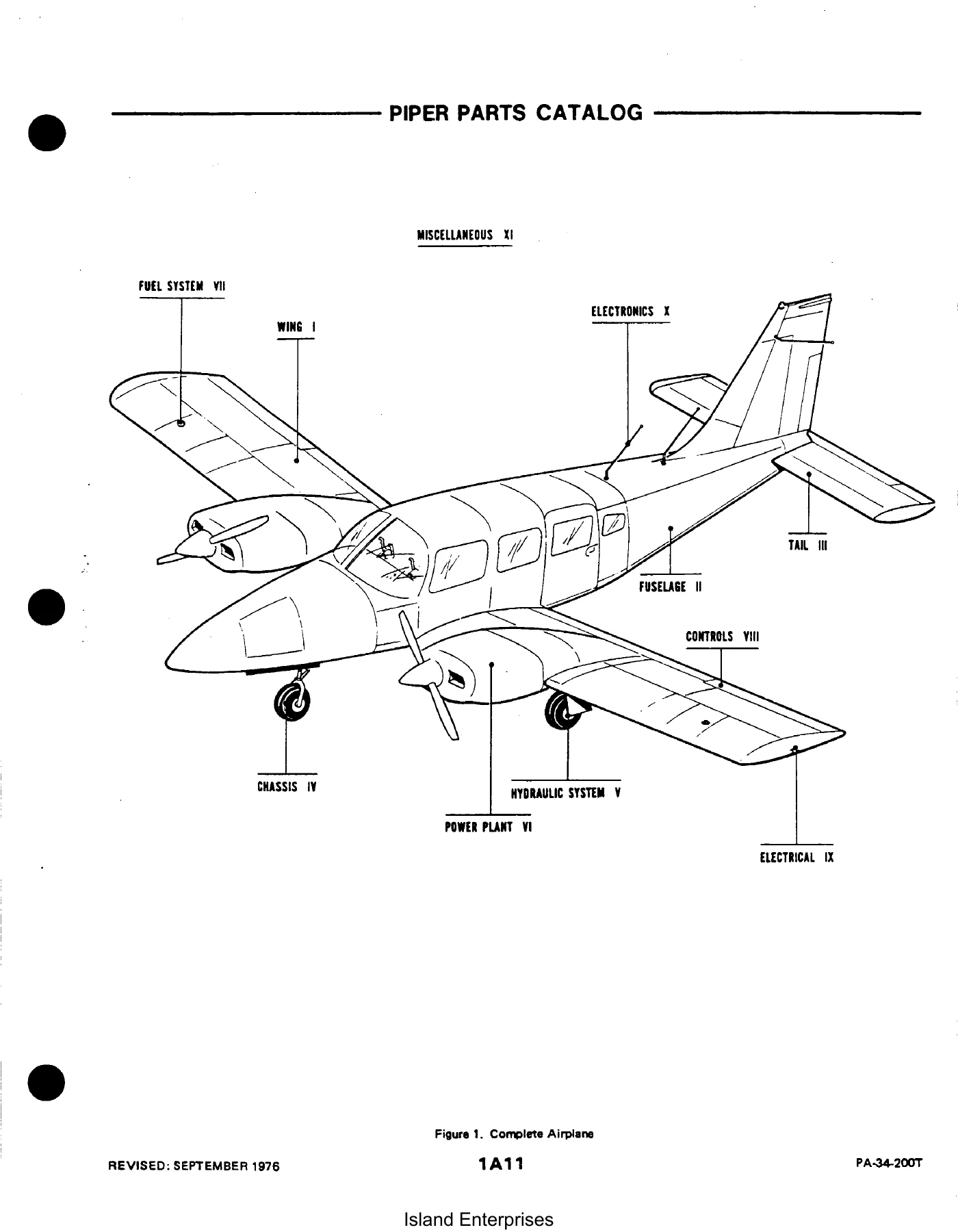
The PA-34-200T Seneca II Parts Catalog is organized around the complete airplane. Figure 1 provides an overview of the aircraft with callouts to each major group, and subsequent figures break the aircraft down into every major system and subsystem.
For the airframe, the wing group covers the complete wing installation including leading and trailing edges, ailerons, and flaps. The fuselage group is the most extensive, documenting everything from the nose cone through the aft fuselage section, including all door assemblies, interior finishing, seats, and environmental systems. The tail surfaces group covers the stabilator, fin, and rudder assemblies with their associated trim tabs and hinges.
For the power plant, the catalog documents the Continental TSIO-360-EB and LTSIO-360-EB engine installations, both Hartzell two-blade and McCauley three-blade propeller assemblies, engine baffles, cowl assemblies, cowl flaps, engine controls, and the complete nacelle installation.
The chassis group covers the nose gear, main gear, wheels, brakes, and the hydraulic system that actuates the landing gear doors. Detailed exploded views show every component from the gear truss assemblies down to individual bushings, bearings, and hardware.
Electrical and electronics coverage includes the complete electrical system, instrument panel electrical, strobe lights, external power supply, landing light, propeller deicer systems, heated glass panel, autopilot installations, ELT systems, radio antenna systems, audio selector, radar altimeter, radar system, and encoder installations.
Why This Illustrated Parts Catalog Is Useful
When maintaining, restoring, or repairing a Seneca II, identifying the correct part is the first step. This catalog gives you the exploded-view illustration that shows how components fit together, the part number to order, the quantity required, and the serial number range that confirms compatibility with your specific aircraft. Without it, you are left guessing or relying on potentially outdated parts listings.
The catalog covers both early and late serial number ranges, with separate part numbers shown where Piper made running changes across the production run. This means you can look up the exact part for your aircraft rather than assuming a single part number applies to all Seneca IIs.
How to Use This Parts Catalog
The catalog is organized so you can work from either direction — find the illustration that shows your system, locate the part visually, then match the index number to the parts listing for the part number and applicability. Or if you already know the part number, use the numerical index at the rear to find its figure and index location.
The serial number column is particularly important. Where a part changed during production, the catalog lists separate part numbers with the specific serial number ranges affected, so you can be confident you are ordering the right component for your aircraft.
Note: This catalog is intended for parts identification only and should not be used for rigging or installation purposes.
Get Your Copy
This Piper PA-34-200T Seneca II Illustrated Parts Catalog gives you the complete parts breakdown for your aircraft, with clear illustrations and accurate part numbers for every system. Whether you are ordering a single replacement part or planning a major restoration, having the right reference saves time, avoids wrong orders, and helps you understand how everything fits together.
IMAGES PREVIEW
Delivered as an instant PDF download after payment — no shipping, no waiting. View it on any device or print the pages you need for the hangar. The entire catalog is in one file, ready to use immediately.
Reviews
There are no reviews yet.