★ TRUSTED BY 321,897+ PROFESSIONALS WORLDWIDE
🏒
Trusted Business
Verified & Licensed
πŸ›‘οΈ
Virus Free Files
100% Safe Downloads
πŸ”’
Secure Payment
SSL Protected
⚑
Instant Delivery
Available Immediately
Sale!

Piper PA-34-220T Seneca III & Seneca IV Illustrated Parts Catalog PDF

Original price was: $34.95.Current price is: $21.95.

Complete illustrated airplane parts catalog for the Piper PA-34-220T Seneca III and Seneca IV, covering every major airframe, engine, systems, cabin, and electrical assembly with figure-indexed part numbers, exploded illustrations, and serial-number effectivity.

⚑
Instant PDF Download
Available immediately
πŸ’Ύ
Save to Your Device
Download & keep forever
πŸ›‘οΈ
Antivirus Scanned
100% virus-free
🌍
Trusted Worldwide
175,000+ customers

Description

Piper PA-34-220T Seneca III & Seneca IV Illustrated Parts Catalog

This is the complete illustrated airplane parts catalog for the Piper PA-34-220T Seneca III and Seneca IV, published by Piper Aircraft Corporation Technical Publications. It is the reference used to identify, look up, and order replacement parts for every major airframe and system assembly on these twin-engine aircraft. Every part in the catalog carries a Piper part number and a figure-and-index reference tied directly to the exploded illustrations, so the correct component can be confirmed visually before ordering. Whether you are maintaining a Seneca III, restoring a Seneca IV, or supporting a fleet, this Piper PA-34-220T Seneca III & Seneca IV Illustrated Parts Catalog is the lookup tool that connects the right part number to the right position on the aircraft.

File Details

  • Manual Type: Illustrated Airplane Parts Catalog
  • Brand / Publisher: Piper Aircraft Corporation β€” Technical Publications, Vero Beach, Florida
  • Aircraft Models: PA-34-220T Seneca III and Seneca IV
  • Language: English
  • File Format: PDF
  • Page Count: 549 pages
  • Publication History: Issued December 15, 1980; kept current with revisions through March 10, 2009
  • Organization: Fourteen major sections, each with its own illustration and parts listing

Chapters Covered

The catalog is divided into sections that mirror the aircraft itself. Each section opens with an exploded illustration and is followed by a parts listing keyed to that figure.

  • Wing Group β€” wing installation, leading edge assemblies, trailing edge assemblies, aileron assembly
  • Fuselage Group β€” complete fuselage, upper and lower cockpit assemblies, forward cabin door, aft cabin door, cargo door, forward baggage door, windows and enclosure
  • Tail Surfaces β€” stabilator, fin, rudder, dorsal fin, tail cone fairings
  • Landing Gear β€” nose gear installation and assembly, main gear installation and assembly, nose wheel, main wheels, brake assembly, toe brake installation
  • Cabin Equipment Group β€” forward baggage compartment finishing, cockpit finishing, window curtains and shades, carpet installation, headliner, seats, vertically adjustable front seat, seventh seat, aft-facing center seat, club seating
  • Instruments Group β€” instrument panel installation (14 V and 28 V), gyro vacuum system, pitot static system
  • Power Plant Group β€” power plant installation, engine baffles, engine cowl, cowl flap, two-blade Hartzell propeller, three-blade McCauley propeller, propeller synchrophaser, propeller unfeathering system, engine controls, quadrant assembly, nacelle installation
  • Fuel System Group β€” wing and fuselage fuel system, engine fuel system, fuel tank assemblies
  • Flight Controls β€” aileron control, rudder control, rudder trim, stabilator control, stabilator trim, flap control (mechanical and electric), control wheel, bobweight, rudder pedal
  • Hydraulic System Group β€” hydraulic system installation
  • Environmental Group β€” heat and defrost, Janitrol heater, heater ducts, heater fuel system, heater controls, aft fresh air duct, air conditioning compressor and refrigerant lines, air conditioning duct and evaporator, air conditioning condenser and scoop, oxygen system, pneumatic deicer
  • Electrical System Group β€” electrical system installation (14 V and 28 V), instrument panel electrical, circuit breaker panel, electrical/avionics switches, ice protection controls, air conditioning electrical, external power supply, battery installation, strobe lights, landing light, propeller electric deicer, heated glass panel
  • Electronics Group β€” Century 21/31/41 autopilot installations, King KFC-200 and KAP 150/KFC 150 autopilot/flight director, Piper automatic locator (ELT 10 and ELT 910), radar altimeter (Bonzer and King), Narco AR 850 encoder, radio antenna system and static wicks, radar systems, electric pitch trim, avionics cooling
  • Miscellaneous Group β€” placards and exterior stencils, optional equipment kits, repair kits, special tools, consumables, avionics installations

Each figure is supported by a parts listing that carries the figure and index number, Piper part number, code, nomenclature, quantity required, and the serial-number effectivity for that part. That last column is what makes this catalog so valuable in practice: it shows at a glance whether a part applies to a specific Seneca III or Seneca IV by serial number, and it flags optional equipment and service-bulletin-linked changes. The introduction also explains the column layout, the indent convention for sub-assemblies, and the code letters used for special uses of a part, so the reader can interpret any listing without guessing.

Complete PDF Bookmark Tree

Complete Bookmarks

The complete bookmarks in the β€œPiper PA-34-220T Seneca III & Seneca IV Illustrated Parts Catalog PDF” are as follows:

761-750 – SENECA III/IV PARTS CATALOG – PA-34-220Tp. 1
REVISION STATUSp. 3
INTRODUCTIONp. 4
EXAMPLEp. 4
GRID NUMBERINGp. 5
HOW TO IDENTIFY A PART IF YOU KNOW WHAT IT LOOKS LIKE AND KNOW WHERE IT IS LOCATEDp. 5
HOW TO ORDER PARTSp. 5
GENERAL INFORMATIONp. 5
PA-34-220T SERIAL NUMBER INFORMATIONp. 6
SERIAL NUMBER EXPLANATIONp. 6
STANDARD PAINT CHARTp. 7
TABLE OF CONTENTSp. 9
FIGURE 1. COMPLETE AIRPLANEp. 15
SECTION I – WING GROUPp. 17
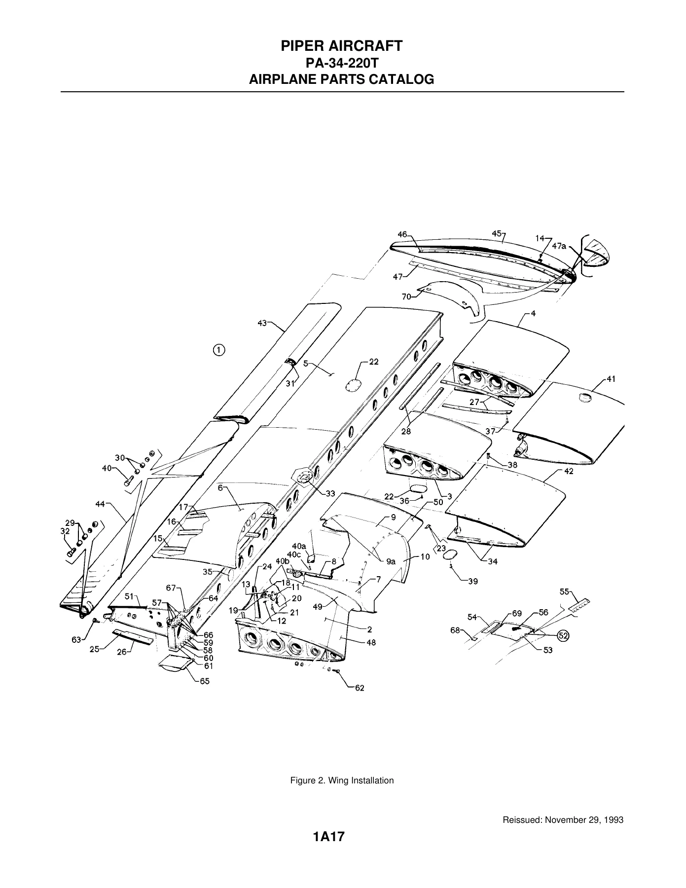
FIGURE 2. WING INSTALLATIONp. 17
FIGURE 3. WING LEADING EDGE ASSEMBLYp. 22
FIGURE 4. WING TRAILING EDGE ASSEMBLYp. 29
FIGURE 5. AILERON ASSEMBLYp. 34
FIGURE 6. FLAP ASSEMBLYp. 37
SECTION II – FUSELAGE GROUPp. 41
FIGURE 7. FUSELAGE ASSEMBLY – COMPLETEp. 41
FIGURE 8. FUSELAGE NOSE CONE ASSEMBLYp. 46
FIGURE 9. FUSELAGE UPPER FORWARD COCKPIT ASSEMBLYp. 49
FIGURE 10. FUSELAGE UPPER CENTER COCKPIT ASSEMBLYp. 54
FIGURE 11. FUSELAGE UPPER AFT COCKPIT ASSEMBLYp. 60
FIGURE 12. FUSELAGE LOWER FORWARD COCKPIT ASSEMBLYp. 63
FIGURE 13. FUSELAGE LOWER AFT COCKPIT ASSEMBLYp. 69
FIGURE 14. FUSELAGE AFT SECTIONp. 73
FIGURE 15. FUSELAGE FORWARD CABIN DOORp. 77
FIGURE 16. FUSELAGE AFT CABIN DOORp. 82
FIGURE 17. FUSELAGE AFT CARGO DOORp. 88
FIGURE 18. FUSELAGE FORWARD BAGGAGE DOOR ASSEMBLYp. 93
FIGURE 19. FUSELAGE ENCLOSURE INSTALLATIONp. 96
SECTION III – TAIL SURFACES GROUPp. 101
FIGURE 20. TAIL SURFACES INSTALLATIONp. 101
FIGURE 21. STABILATOR ASSEMBLYp. 105
FIGURE 22. FIN ASSEMBLYp. 109
FIGURE 23. RUDDER ASSEMBLYp. 112
SECTION IV – LANDING GEAR GROUPp. 115
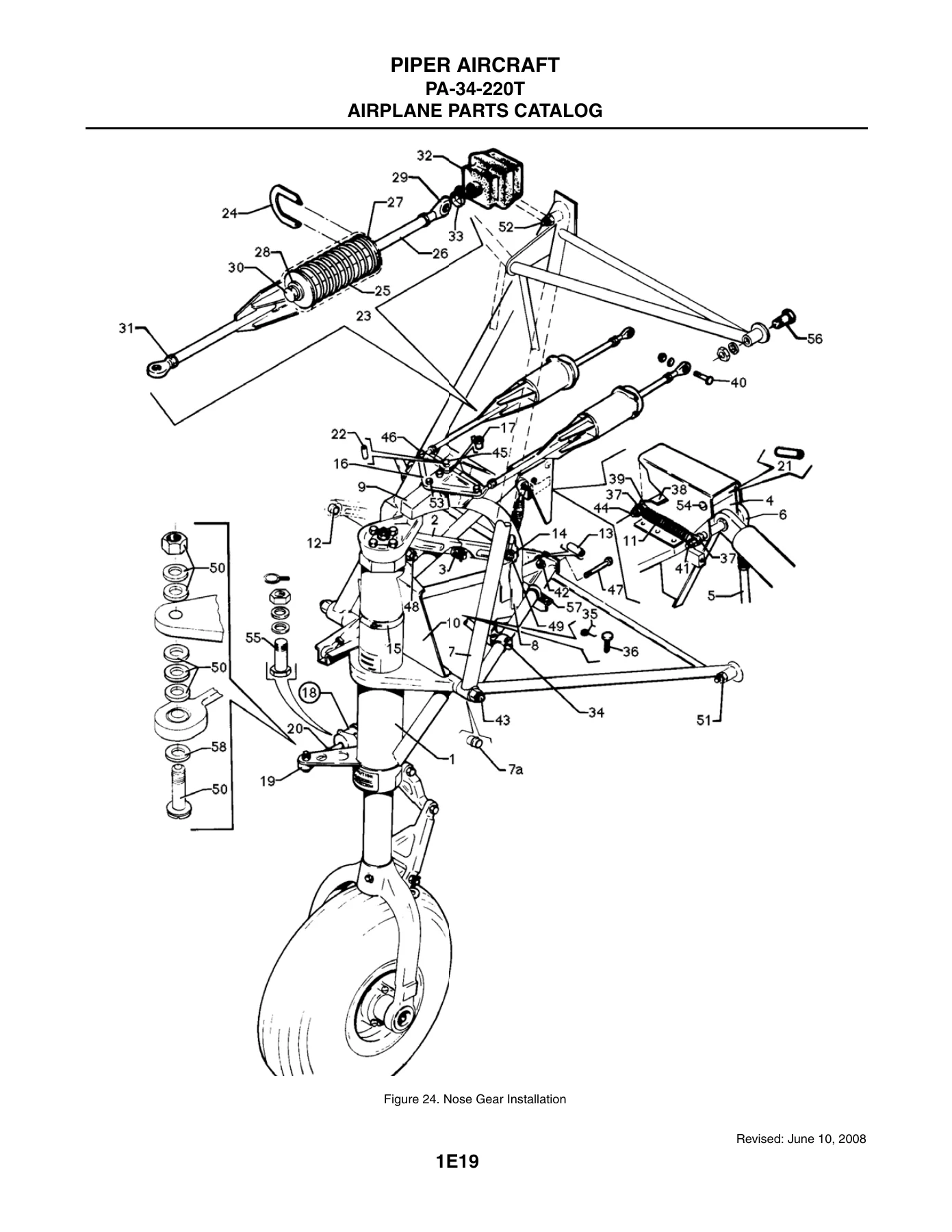
FIGURE 24. NOSE GEAR INSTALLATIONp. 115
FIGURE 25. NOSE GEAR ASSEMBLYp. 119
FIGURE 26. NOSE WHEEL ASSEMBLY (CLEVELAND)p. 123
FIGURE 26A. NOSE WHEEL ASSEMBLY (MCCAULEY)p. 126
FIGURE 27. MAIN GEAR INSTALLATIONp. 129
FIGURE 28. MAIN GEAR ASSEMBLYp. 133
FIGURE 29. MAIN WHEEL ASSEMBLY (CLEVELAND)p. 137
FIGURE 30. BRAKE ASSEMBLYp. 140
FIGURE 31. NOSE AND MAIN GEAR DOOR ACTUATION INSTALLATIONSp. 143
FIGURE 32. BRAKE SYSTEM INSTALLATIONp. 147
FIGURE 33. TOE BRAKE INSTALLATIONp. 150
FIGURE 34. TOE BRAKE MASTER CYLINDER ASSEMBLYp. 153
SECTION V – CABIN EQUIPMENT GROUPp. 157
FIGURE 35. FORWARD BAGGAGE COMPARTMENT FINISHING INSTALLATIONp. 157
FIGURE 36. COCKPIT FINISHING INSTALLATIONp. 160
FIGURE 36A. COCKPIT FINISHING INSTALLATION (SERIAL NUMBERS 3448038 AND UP)p. 166
FIGURE 37. WINDOW CURTAINS INSTALLATIONp. 169
FIGURE 37A. WINDOW SHADES AND REVEALS INSTALLATION (SERIAL NUMBERS 3448038 AND UP)p. 172
FIGURE 38. CARPET INSTALLATIONp. 175
FIGURE 39. FORWARD FRESH AIR DUCT AND HEADLINER INSTALLATIONp. 181
FIGURE 39A. FORWARD FRESH AIR DUCT AND HEADLINER INSTALLATION (SERIAL NUMBERS 3448038 AND UP)p. 184
FIGURE 40. SEATS INSTALLATIONp. 190
FIGURE 41. VERTICALLY ADJUSTABLE FRONT SEAT ASSEMBLYp. 196
FIGURE 42. 7TH SEAT INSTALLATIONp. 201
FIGURE 43. AFT FACING SEAT ASSEMBLY – CENTERp. 204
FIGURE 44. CLUB SEATING INSTALLATIONp. 207
SECTION VI – INSTRUMENT GROUPp. 213
FIGURE 45. INSTRUMENT PANEL INSTALLATIONp. 213
FIGURE 45A. INSTRUMENT PANEL INSTALLATION (28 VOLT SYSTEM, INCLUDES SERIAL NUMBERS 3448001 THRU 3448037)p. 217
FIGURE 45B. INSTRUMENT PANEL INSTALLATION (SERIAL NUMBERS 3448038 AND UP)p. 221
FIGURE 46. GYRO VACUUM SYSTEM INSTALLATIONp. 225
FIGURE 47. PITOT STATIC SYSTEM INSTALLATIONp. 228
SECTION VII – POWER PLANT GROUPp. 233
FIGURE 48. POWER PLANT INSTALLATIONp. 233
FIGURE 49. ENGINE INSTRUMENT LINES INSTALLATIONp. 237
FIGURE 50. ENGINE BAFFLE INSTALLATIONp. 241
FIGURE 51. ENGINE COWLING ASSEMBLYp. 246
FIGURE 52. COWL FLAP INSTALLATIONp. 249
FIGURE 53. TWO BLADE PROPELLER ASSEMBLY (HARTZELL)p. 252
FIGURE 54. THREE BLADE PROPELLER ASSEMBLY (MCCAULEY)p. 255
FIGURE 55. PROPELLER SYNCHROPHASER SYSTEM INSTALLATION (S/N 34-8133002 THRU 34-8133195)p. 259
FIGURE 55A. PROPELLER SYNCHROPHASER SYSTEM INSTALLATION (S/N 34-8133001, 34-8133196 AND UP, 3448001 AND UP)p. 262
FIGURE 55B. PROPELLER UNFEATHERING SYSTEM INSTALLATION (S/N 34-8333001 AND UP, 3448001 AND UP)p. 265
FIGURE 56. ENGINE CONTROLS INSTALLATIONp. 270
FIGURE 57. QUADRANT ASSEMBLYp. 274
FIGURE 58. NACELLE INSTALLATIONp. 277
SECTION VIII – FUEL SYSTEM GROUPp. 281
FIGURE 59. FUEL SYSTEM INSTALLATION – WING AND FUSELAGEp. 281
FIGURE 60. FUEL SYSTEM INSTALLATION – ENGINEp. 285
FIGURE 61. FUEL TANK ASSEMBLIESp. 288
SECTION IX – CONTROL SYSTEM GROUPp. 293
FIGURE 62. AILERON CONTROL INSTALLATIONp. 293
FIGURE 63. RUDDER CONTROL INSTALLATIONp. 297
FIGURE 64. RUDDER TRIM INSTALLATIONp. 300
FIGURE 65. STABILATOR CONTROL INSTALLATIONp. 306
FIGURE 66. STABILATOR TRIM INSTALLATIONp. 309
FIGURE 67. FLAP CONTROL INSTALLATION (S/N 34-8133001 THRU 34-8433086)p. 313
FIGURE 67A. FLAP CONTROL INSTALLATION (S/N 34-8533001 AND UP, 3448001 AND UP)p. 317
FIGURE 68. CONTROL WHEEL INSTALLATIONp. 321
FIGURE 69. BOBWEIGHT INSTALLATIONp. 325
FIGURE 70. RUDDER PEDAL INSTALLATIONp. 330
SECTION X – HYDRAULIC SYSTEM GROUPp. 335
FIGURE 71. HYDRAULIC SYSTEM INSTALLATIONp. 335
SECTION XI – ENVIRONMENTAL GROUPp. 341
FIGURE 72. HEAT AND DEFROST SYSTEM INSTALLATIONp. 341
FIGURE 73. JANITROL HEATER ASSEMBLYp. 344
FIGURE 74. JANITROL HEATER COMPONENTSp. 347
FIGURE 75. HEATER DUCT INSTALLATIONp. 350
FIGURE 76. HEATER FUEL SYSTEM INSTALLATIONp. 353
FIGURE 77. HEATER CONTROLS INSTALLATIONp. 358
FIGURE 78. AFT FRESH AIR DUCT INSTALLATIONp. 361
FIGURE 79. AIR CONDITIONING COMPRESSOR AND REFRIGERANT LINES INSTALLATIONp. 364
FIGURE 80. AIR CONDITIONING DUCT AND EVAPORATOR INSTALLATIONp. 367
FIGURE 81. AIR CONDITIONING CONDENSER AND SCOOP INSTALLATION (14 VOLT SYSTEM)p. 370
FIGURE 81A. AIR CONDITIONING CONDENSER AND SCOOP INSTALLATION (28 VOLT SYSTEM)p. 374
FIGURE 82. OXYGEN SYSTEM INSTALLATION (FIXED)p. 377
FIGURE 82A. OXYGEN SYSTEM INSTALLATIONp. 384
FIGURE 83. PNEUMATIC DEICER INSTALLATION (14 VOLT SYSTEM)p. 387
FIGURE 83A. PNEUMATIC DEICER INSTALLATION (28 VOLT SYSTEM)p. 391
SECTION XII – ELECTRICAL SYSTEM GROUPp. 395
FIGURE 84. ELECTRICAL SYSTEM INSTALLATION (14 VOLT SYSTEM)p. 395
FIGURE 84A. ELECTRICAL SYSTEM INSTALLATION (28 VOLT SYSTEM)p. 399
FIGURE 85. INSTRUMENT PANEL ELECTRICAL INSTALLATION (14 VOLT SYSTEM)p. 403
FIGURE 85A. INSTRUMENT PANEL ELECTRICAL INSTALLATION (28 VOLT SYSTEM)p. 410
FIGURE 85B. CIRCUIT BREAKER PANEL ASSEMBLY (28 VOLT SYSTEM)p. 414
FIGURE 85C. ELECTRICAL/AVIONICS SWITCHES (SERIAL NUMBERS 3448038 AND UP)p. 417
FIGURE 85D. ICE PROTECTION SYSTEM CONTROLS (SERIAL NUMBERS 3448038 AND UP)p. 420
FIGURE 86. AIR CONDITIONING ELECTRICAL INSTALLATIONp. 423
FIGURE 87. EXTERNAL POWER SUPPLY INSTALLATION (14 VOLT SYSTEM)p. 426
FIGURE 87A. EXTERNAL POWER SUPPLY INSTALLATION (28 VOLT SYSTEM)p. 429
FIGURE 87B. BATTERY INSTALLATION (28 VOLT SYSTEM)p. 432
FIGURE 88. STROBE LIGHTS INSTALLATION (14 VOLT SYSTEM)p. 435
FIGURE 88A. STROBE LIGHTS INSTALLATION (28 VOLT SYSTEM)p. 441
FIGURE 89. LANDING LIGHT INSTALLATIONp. 444
FIGURE 90. TWO BLADE PROPELLER ELECTRIC DEICER INSTALLATIONp. 447
FIGURE 91. THREE BLADE PROPELLER ELECTRIC DEICER INSTALLATIONp. 450
FIGURE 92. HEATED GLASS PANEL INSTALLATIONp. 453
SECTION XIII – ELECTRONICS GROUPp. 457
FIGURE 93. CENTURY 21 AUTOPILOT INSTALLATIONp. 457
FIGURE 93A. CENTURY 41 AUTOPILOT INSTALLATION (S/N 34-8133010 AND UP)p. 460
FIGURE 93B. CENTURY 31 AUTOPILOT INSTALLATION (S/N 34-8433001 AND UP)p. 463
FIGURE 93C. KING KFC-200 AUTOPILOT/FLIGHT DIRECTOR INSTALLATIONp. 466
FIGURE 93D. KING KAP 150/KFC 150 AUTOPILOT/FLIGHT DIRECTOR INSTALLATION (S/N 34-8433001 AND UP)p. 469
FIGURE 94. PIPER AUTOMATIC LOCATOR (ELT-10) INSTALLATION (NARCO AVIONICS)p. 472
FIGURE 94A. PIPER AUTOMATIC LOCATOR (ELT-910) (NARCO AVIONICS) AND (ELT 110-4 ARTEX) INSTLp. 475
FIGURE 95. RADAR ALTIMETER INSTALLATION (BONZER)p. 478
FIGURE 96. RADAR ALTIMETER INSTALLATION (KING)p. 481
FIGURE 97. ENCODER INSTALLATION (NARCO AR 850)p. 484
FIGURE 98. RADIO ANTENNA SYSTEM AND STATIC WICKS INSTALLATIONp. 487
FIGURE 99. RADAR SYSTEM INSTALLATION (RCA WEATHERSCOUT II, BENDIX RDR-160 AND RDS-82, AND KING KWX-56)p. 490
FIGURE 99A. ELECTRIC PITCH TRIM INSTALLATION (S/N 34-8433050 AND UP)p. 493
FIGURE 100. AVIONICS COOLING INSTALLATION (TYPICAL)p. 496
SECTION XIV – MISCELLANEOUS GROUPp. 501
FIGURE 101. PLACARDS AND EXTERIOR STENCILSp. 501
OPTIONAL EQUIPMENT KITS, REPAIR KITS, SPECIAL TOOLS AND MISCELLANEOUS HARDWAREp. 509
CONSUMABLESp. 510
AVIONICS INSTALLATIONSp. 512
NUMERICAL INDEXp. 514

What This Parts Catalog Does for You

A parts catalog is not a repair guide β€” it is the identification tool that keeps every repair, inspection, and rebuild on the right part. With this Piper PA-34-220T Seneca III & Seneca IV Illustrated Parts Catalog, you can locate the exact part number for a component by working from the illustration to the listing, confirm that the part applies to the aircraft’s serial number range, and check whether a related kit or optional-equipment variant changes the part required. That matters on a twin like the Seneca, where the same assembly can carry different part numbers depending on whether air conditioning, oxygen, a synchrophaser, or a specific propeller installation is fitted.

The exploded drawings also make excellent visual references during teardown and reassembly. Being able to see the order of components, the orientation of fittings, and the hardware that attaches an assembly saves time on the bench and reduces the risk of installing the wrong piece. For owners working with a shop, arriving with the correct figure and index number turns a vague request into a precise part order that the distributor can fill on the first try.

The catalog also documents the parts that surround the aircraft rather than the structure itself β€” placards and exterior stencils, baggage tie-downs, sun visors, cup holders, seat belts and shoulder harnesses, and the optional equipment kits that Piper released over the life of the type. That makes it useful for owners chasing down cosmetic items and for restorers trying to return a Seneca to the configuration it left the factory with.

IMAGES PREVIEW

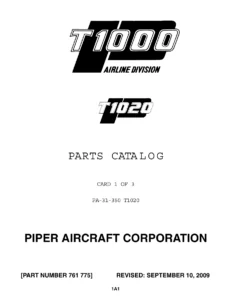
Piper PA-34-220T Seneca III & Seneca IV Illustrated Parts Catalog PDF β€” PDF page 1 preview
Piper PA-34-220T Seneca III & Seneca IV Illustrated Parts Catalog PDF β€” PDF page 17 preview
Piper PA-34-220T Seneca III & Seneca IV Illustrated Parts Catalog PDF β€” PDF page 115 preview

Instant PDF Delivery

This Piper PA-34-220T Seneca III & Seneca IV parts catalog is delivered as a downloadable PDF. There is no printed book to ship and no waiting: the file is available immediately after purchase and can be opened on a phone, tablet, laptop, or desktop computer. Pages can be printed for the hangar or shop and marked up freely, and the file can be stored in a maintenance folder alongside the airframe logbooks. Because the catalog is organized by figure and index number, jumping between the illustration and the parts listing is straightforward, and the layout makes it easy to look up a part number or nomenclature when a component is already in hand.

If you maintain, repair, or restore a Piper PA-34-220T Seneca III or Seneca IV, this illustrated parts catalog belongs in your technical library β€” it is the fastest way to go from a part on the aircraft to the part number you need to order.

Reviews

There are no reviews yet.

Be the first to review “Piper PA-34-220T Seneca III & Seneca IV Illustrated Parts Catalog PDF”

What Our Customers Say

β˜…β˜…β˜…β˜…β˜… Live reviews from customers
Loading customer reviews...
0
    0
    Your Cart
    Your cart is emptyReturn to Shop
    πŸ›’
    Recently Purchased
    πŸ•’ verified order