
Piper PA-46-310P Malibu & PA-46-350P Malibu Mirage Airplane Parts Catalog – Revised 2006
Original price was: $39.95.$24.95Current price is: $24.95.
Illustrated 678-page parts catalog for the Piper Malibu PA-46-310P and Malibu Mirage PA-46-350P, revised September 10, 2006. Covers illustrated assemblies, part numbers, nomenclature, quantities, serial-number effectivity, power plant, landing gear, controls, hydraulics, electrical, environmental, electronics, and miscellaneous equipment.
Description
Piper PA-46-310P Malibu & PA-46-350P Malibu Mirage Airplane Parts Catalog – Revised 2006
This illustrated airplane parts catalog is a detailed replacement-parts reference for the Piper PA-46-310P Malibu and PA-46-350P Malibu Mirage. The catalog identifies assemblies and individual components with figure and index references, part numbers, nomenclature, quantities required, applicable codes, and serial-number effectivity. Revised September 10, 2006, it brings together airframe, landing gear, cabin, power plant, fuel, flight-control, hydraulic, environmental, electrical, electronics, and miscellaneous parts information in one extensive reference.
The Piper PA-46-310P Malibu & PA-46-350P Malibu Mirage Airplane Parts Catalog – Revised 2006 is especially useful when the task is to identify a replacement component from an illustration and then confirm the corresponding part listing. The catalog explains the relationship between illustrated figure numbers and indexed parts, while indentation in the nomenclature shows how smaller items relate to higher-level assemblies. Serial-number columns help distinguish parts that apply only to particular aircraft ranges or model configurations.
File Details
- Manual type: Airplane Parts Catalog
- Brand: Piper Aircraft
- Models: Malibu PA-46-310P and Malibu Mirage PA-46-350P
- Language: English
- Page count: 678 pages
- File format: PDF
- Part number: 761 782
- Revision: Revised September 10, 2006
Model, Serial Number and Power Plant Coverage
The cover identifies PA-46-310P Malibu coverage for S/N 46-8408001 thru 46-8608067 and 4608001 thru 4608140, and PA-46-350P Malibu Mirage coverage for S/N 4622001 thru 4622200. Within the catalog, individual listings add more specific serial-number effectivity where parts changed during production. This makes the catalog useful not only for locating a component family, but also for checking which version of an assembly or attaching part is listed for a particular aircraft.
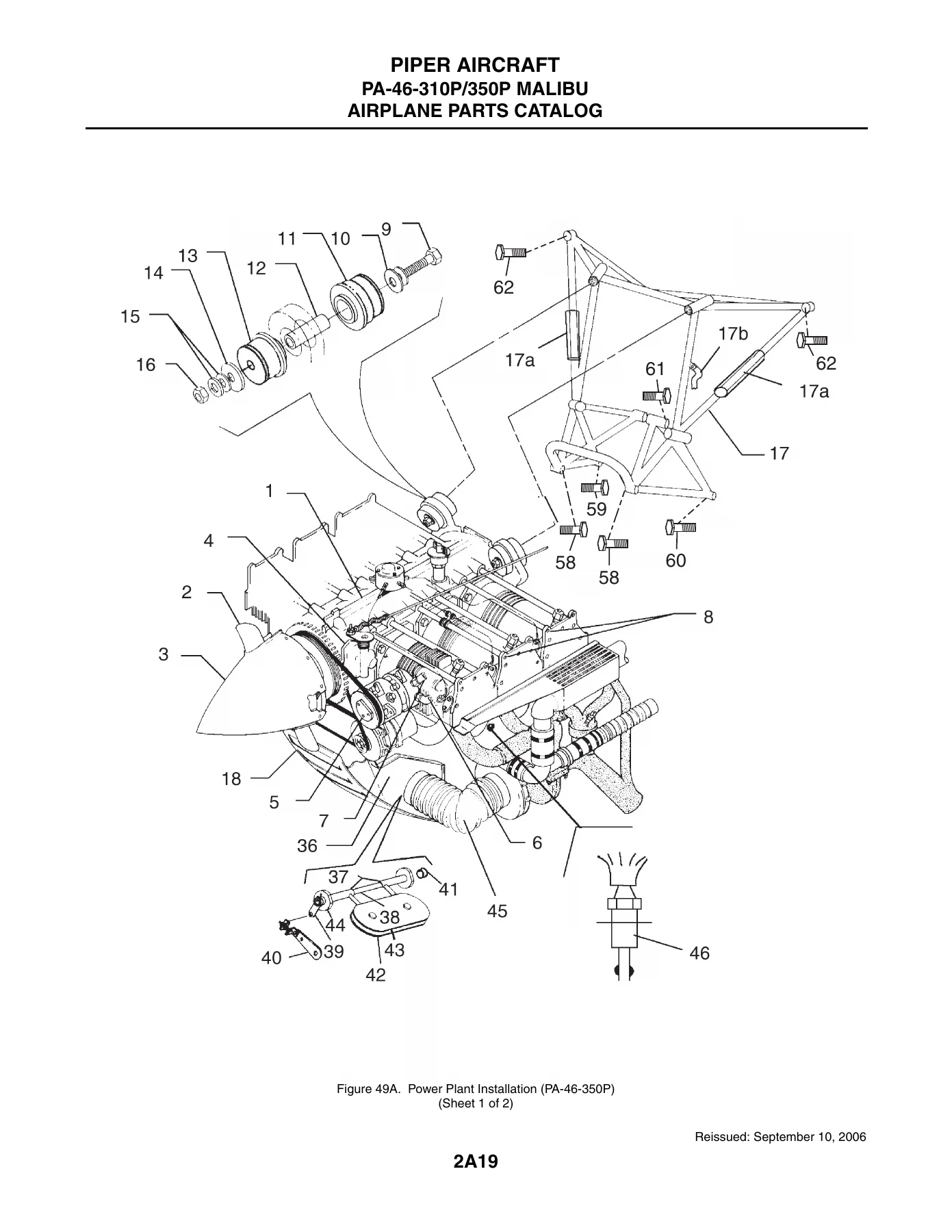
Power plant pages identify a Continental TSIO-520-BE engine assembly for the PA-46-310P installation and a Lycoming TIO540-AE2A engine assembly for the PA-46-350P installation. Separate illustrated coverage is also provided for Hartzell two-blade propeller assemblies used with the two models, along with engine controls, baffles, cowling, instrument lines, induction-related items, and associated installation hardware.
How the Illustrated Parts Information Is Organized
The catalog is arranged around illustrations followed by detailed parts listings. A figure and index number links the callout shown on an illustration to the corresponding line in the parts list. The parts-list columns identify the part number, special-use code when applicable, part nomenclature, quantity required, and serial numbers affected. Assembly relationships are shown through indentation, allowing the reader to see whether an item belongs beneath a larger assembly. The catalog also includes notes and code explanations that point to model-specific applications, service bulletins, service letters, kits, or alternative component configurations.
This is a parts-identification catalog rather than a rigging or installation manual. The catalog itself specifically states that it is not to be used for rigging and installation purposes. Its strength is the illustrated identification of replacement parts, assembly relationships, quantities, model differences, and serial-number applicability.
Chapters Covered
- Section I – Wing Group
- Inboard wing installation
- Wing-to-fuselage fairing installation
- Outboard wing installation
- Aileron installation
- Flap installation
- Section II – Fuselage Group
- Complete fuselage assembly
- Forward baggage compartment assemblies for PA-46-310P and PA-46-350P
- Forward, center, and aft cockpit structure
- Rear fuselage and floorboard installations
- Cabin entrance, upper and lower cabin, emergency, and forward baggage doors
- Fuselage enclosure and window installations
- Section III – Tail Surfaces Group
- Tail surfaces installation
- Fin assembly
- Rudder assembly
- Stabilizer assembly
- Elevator assembly
- Section IV – Landing Gear Group
- Nose gear installation and assembly
- Gar-Kenyon and Parker Hannifin nose gear locking actuators
- Cleveland and McCauley nose wheel assemblies
- Main gear installation and assembly
- Main gear locking actuators
- Main wheel and brake assemblies
- Nose and main gear door actuation, brake system, and toe brake installations
- Section V – Cabin Equipment Group
- Cockpit finishing and side panels
- Window frame, curtain, sun visor, and cabin carpet installations
- Seat installations and front, center, and aft seat assemblies
- Relief tube installation
- Section VI – Instruments Group
- Instrument panel installations for PA-46-310P and PA-46-350P
- Vacuum system configurations
- Pitot-static system installation
- Section VII – Power Plant Group
- Power plant installations for PA-46-310P and PA-46-350P
- Engine instrument lines
- Engine baffle and cowl installations
- Hartzell two-blade propeller assemblies
- Engine controls installations
- Section VIII – Fuel System Group
- Fuel system installations for PA-46-310P and PA-46-350P
- Fuel system components
- Section IX – Control System Group
- Control console and quadrant
- Aileron, rudder, and aileron-rudder interconnect systems
- Elevator and elevator trim
- Electrical flap drive configurations
- Control wheel installation
- Section X – Hydraulic System Group
- Forward, center, and aft hydraulic installations
- Gar-Kenyon and Parker-Hannifin component configurations
- Landing gear selector, timed check, sequence, and emergency release valves
- Hydraulic pump assemblies
- Hydraulic flap drive installation
- Section XI – Environmental Group
- Cabin air and pressurization systems
- Bleed air and conditioning installations
- Bleed and ram air selector and temperature-control components
- Air-conditioning compressor, Freon lines, evaporator, and condenser
- Pneumatic deicing and oxygen systems
- Section XII – Electrical System Group
- Forward, center, and aft electrical installations
- Instrument-panel electrical installations and circuit-breaker panels
- Battery and external power
- Landing, navigation, and strobe lights
- Propeller heat and heated-glass installations
- Alternator installation
- Section XIII – Electronics Group
- RCA Weatherscout 1 radar and RDR 2000 VP weather radar installations
- King KAP 150/KFC 150 autopilot and flight director installation
- Antenna, static wicks, and stereo installation
- Emergency locator transmitter installation
- Avionics cooling and radio installation drawings
- Section XIV – Miscellaneous Group
- Placards and decals
- Optional equipment kits and repair kits
- Miscellaneous hardware and consumables
- Numerical index
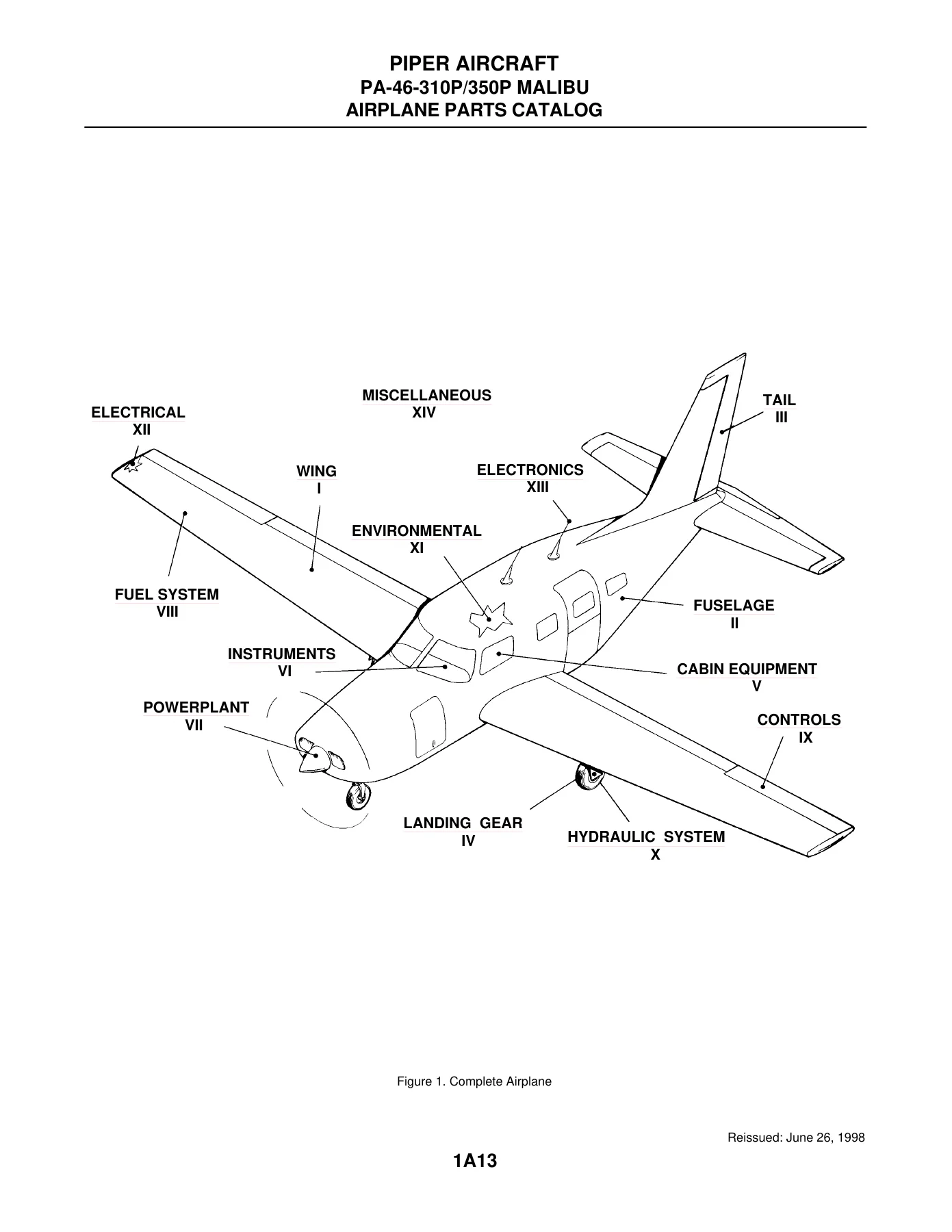
Across these sections, the catalog moves from complete-aircraft and major-system illustrations down to detailed assemblies and individual hardware. Examples include wing skins, spars and ribs; cabin and baggage doors; landing gear actuators and wheel assemblies; propeller components; flight-control linkages; hydraulic valves and pumps; pressurization, air-conditioning and oxygen components; electrical panels and lighting; radar, autopilot and avionics-related installations; and model-specific kits. Many illustrations are paired with code-explanation pages that clarify alternatives for the PA-46-310P and PA-46-350P or identify serial-number-dependent changes.
Illustrated Part Identification and Effectivity
A major advantage of this PA-46 Malibu and Malibu Mirage parts catalog is the density of illustrated assembly drawings. Callouts on wing, fuselage, door, tail, landing gear, power plant and system diagrams correspond directly to parts-list entries. That structure helps a technician or owner move from a visible component or assembly location to a part number, then check quantity and aircraft effectivity before sourcing a replacement. The later miscellaneous material extends the reference beyond the main airframe groups with optional-equipment kits, repair kits, special tools, hardware, consumables, placards and decals.
The catalog also documents numerous supplier or configuration distinctions, including Gar-Kenyon and Parker Hannifin hydraulic and landing-gear components, Cleveland and McCauley nose-wheel assemblies, and model-specific electrical, environmental and electronics installations. These distinctions matter when two aircraft in the PA-46 family use different assemblies even though the system serves the same general function.
Identify the Correct Piper PA-46 Parts with Confidence
The Piper PA-46-310P Malibu & PA-46-350P Malibu Mirage Airplane Parts Catalog – Revised 2006 supports detailed parts identification across the aircraft, from structural assemblies and doors to landing gear, power plant, controls, hydraulics, pressurization, electrical equipment and avionics-related installations. It is particularly valuable when you need the illustrated relationship between components, the listed part number and nomenclature, the quantity used, and the serial-number effectivity before ordering or planning parts replacement. Using the correct model and effectivity information helps reduce confusion between similar-looking assemblies and production changes.
Purchase provides instant PDF delivery with no physical shipping. The file can be opened on compatible phones, tablets, laptops, and desktop computers, and pages can be printed when a paper reference is more convenient in the hangar or workshop.
Reviews
There are no reviews yet.