
Raymond 7500 7520 Reach-Fork Lift Truck Maintenance Manual – Publication 1112860C
Original price was: $39.95.$24.95Current price is: $24.95.
Complete Raymond 7500/7520 Reach-Fork lift truck maintenance manual, publication 1112860C issued 09 May 2016, covering scheduled maintenance, troubleshooting, fault codes, hydraulic and electrical diagnostics, and component-level repair procedures for trucks from serial number 31,001 and up.
Description
Raymond 7500 7520 Reach-Fork Lift Truck Maintenance Manual – Publication 1112860C
This Raymond 7500 7520 Reach-Fork Lift Truck Maintenance Manual, publication 1112860C, applies to Models 7500 and 7520 Reach-Fork lift trucks from serial number 31,001 and up. It is the full maintenance, diagnostic, and component-procedure reference for the truck, written for technicians who need the actual settings, pressures, fault-code meanings, torque figures, and step-by-step teardown sequences rather than a general overview. The manual runs across eleven major sections plus a schematics set, and it covers three separate drivetrain configurations: standard AC lift, AC lift with regenerative lower, and DC lift.
File Details
- Manual type: Maintenance Manual
- Brand: Raymond
- Models covered: 7500 and 7520 Reach-Fork lift trucks
- Serial number range: 31,001 and up
- Publication number: 1112860C
- Revision: 1112860C issued 09 May 2016 (supersedes 1112860B, 28 Oct 2013, and 1112860A, 15 Feb 2012)
- Language: English
- File format: PDF
- Page count: 497 pages
Chapters Covered
- How to Use This Manual – manual design, Interactive Electronic Technical Manuals, abbreviations and symbols
- Safety – definitions, general safety, battery safety, static precautions, jacking safety, tie-down for transport, welding safety
- Systems Overview – lift truck specifications, model designations, general information, truck installation, FlashWare, operator display, modes of operation
- Scheduled Maintenance – maintenance guidelines, Maintenance Minder tool, initial 90 day/250 deadman hour service, every 180 days or 500 HD, every 360 days or 2000 HD, lubrication points, contactor tip inspection, chain maintenance, fork inspection
- Troubleshooting – electrical troubleshooting, troubleshooting power amplifier error codes, hydraulic troubleshooting guidelines, symptom tables for hydraulic functions, travel functions, and electrical symptoms
- Messages, Codes, and Tests – power amp LED diagnostics, messages and codes, analog tests, input tests, output tests
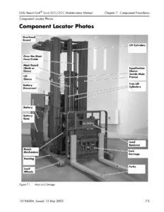
- Component Procedures – component locator photos, special tools, decals and chassis, steering and controls, drive and brake, electrical components, hydraulic components, hydraulic cylinders, mast, chain, hose and cable
- Theory of Operation – traction system functional operation, cold storage, hydraulic system functional operation for each lift configuration, electric brake operation, pinout matrix
- Appendix – lubrication specification chart, thread adhesives, sealants and lubricants, component specific service/torque chart, torque charts for hydraulic fittings, face seal O-rings, ferrous and brass fasteners, thread-forming screws, decimal equivalent chart, standard/metric conversions
- Index
- Schematics – power distribution diagrams, electrical schematics, hydraulic schematics
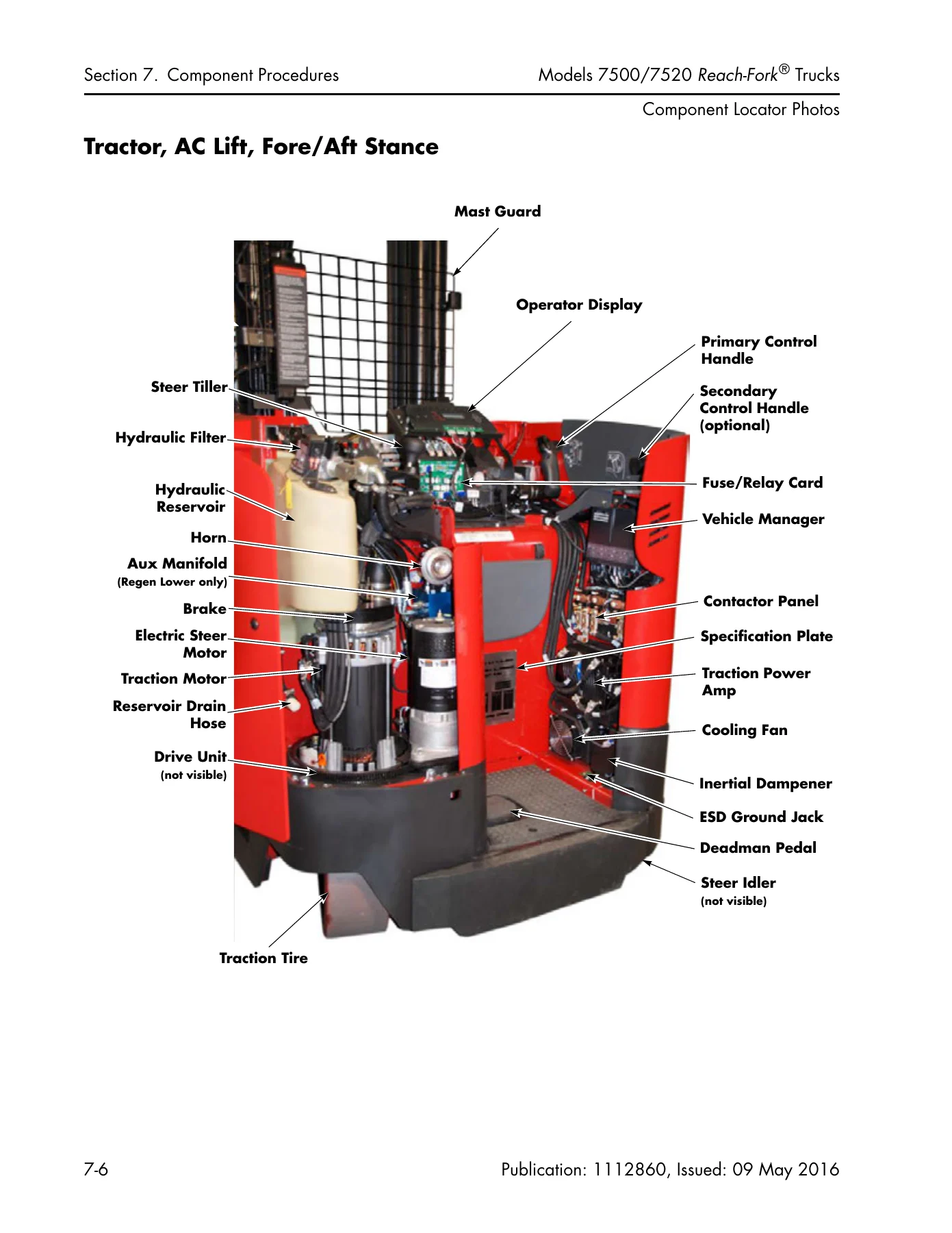
Put together, the sections move from what the truck is, to what it should be doing, to what to do when it is not. The Systems Overview establishes the model designation logic, so you can tell a 750A from a 750C from a 750D by tractor series, lift system, and operator stance, and it documents the operator display, the two run modes, and the configure and service menus. The Theory of Operation chapter then explains what the signals and hydraulic flows are actually doing during traction, lift, lower, and every auxiliary function, with a full pinout matrix listing normal voltages, signal sources, and signal users for the major connectors.
Scheduled Maintenance
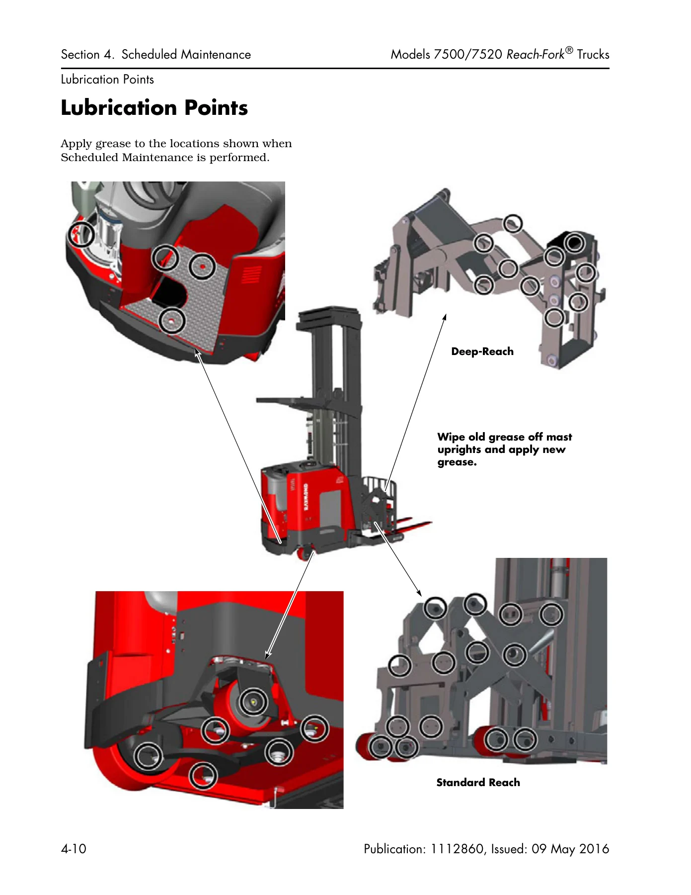
The scheduled maintenance chapter is built around deadman hours rather than calendar time alone, and it splits the workload across an initial 90 day or 250 HD service, a recurring 180 day or 500 HD service, and a 360 day or 2000 HD service. Tasks include drive unit fluid changes and mounting bolt re-torquing, mast-to-tractor bolt break-free and re-torque, power amplifier terminal nut torque, hydraulic reservoir and filter service, brake stopping-distance checks, air gap measurement, contactor tip inspection, static strap resistance checks, steer caster adjustment, lubrication of all grease points, and lift chain gauging. Fork inspection is documented in full, including blade and shank straightness, fork angle against the caliper indicator lines, fork tip height, hook and pocket wear, and marking legibility, with the wear thresholds and the caliper part numbers given.
Troubleshooting and Diagnostics
The troubleshooting material is organized so you start from a symptom rather than a component. Symptom tables cover auxiliary functions, the lift and lower system, and travel functions, each listing probable causes paired with the specific test or corrective action to run. Intermittent faults, no-lift conditions, slow lift, load drift and settling, slow or sluggish acceleration, and slow travel all have their own entries. Electrical troubleshooting covers shorts to frame in detail, including the test-light and DMM procedures for battery case leakage, truck B+ and B- leakage, and the acceptable current thresholds. The power amplifier error code section decodes the sub-codes behind codes AP, AT, 5G, and 5J, and the messages and codes chapter gives the title, reason, test to run, and corrective action for each code from 1H through X4.
Diagnostic Tests
The Messages, Codes, and Tests chapter contains the analog, input, and output test procedures in full. Analog tests cover the primary and secondary throttle potentiometers, lift and lower potentiometer, traction and lift motor temperatures, TPA and LPA temperatures, motor currents, pressure sensor voltage, the 12 VDC and 5 VDC supplies, battery voltage, brake armature, ambient air temperature, steer power amp current, handle heater reference voltage, EPO switch, and the learned travel and lift potentiometer values. Input tests cover the deadman switch, nested switch, first speed limiting switch, reach and retract switches, tilt up and down, sideshift left and right, steering fuse, horn switch, traction and lift motor speed sensors, lift cutout switch, CAN bus, steer feedback proximity sensor, steer motor encoder, height indicator encoder, and the optional security start switch. Output tests cover the TPC or MPC contactor, STR contactor, LPC contactor, AUX contactor, each directional solenoid, the reach, tilt, and sideshift solenoids, the aux dump and main relief dump, load hold, proportional lower ramp, horn, audible alarm, travel alarm, cooling fans, second pump solenoid, lift motor ramp, traction motor ramp, brake coil, relays K1 through K4, and the customer output.
Component Procedures
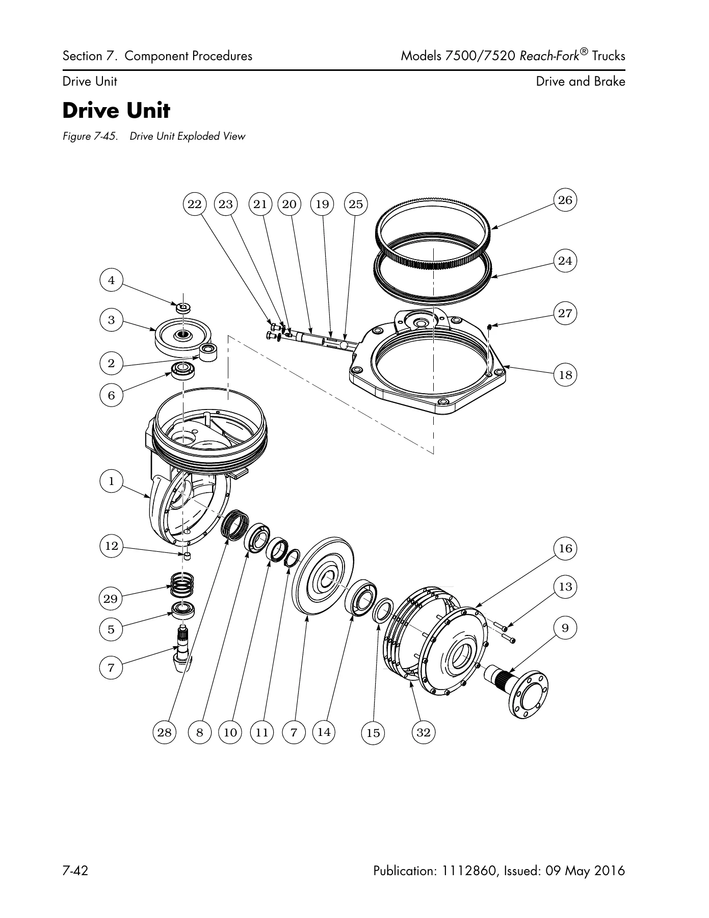
For actual repair work, the component procedures section walks through removal, disassembly, reassembly, and installation of the major assemblies. Drive unit coverage includes the complete exploded view, radial ring inspection, drive unit removal and installation, disassembly and assembly, shim calculation formulas, backlash measurement, helical gear and spiral pinion setup, pivot ring and radial ring service, and drive tire pressing. Brake coverage includes air gap inspection, removal, pad replacement, coil replacement, and installation with the specified torque values. Steering and control coverage includes the steer tiller encoder, steer limit switch vertical and lateral adjustment, steerable caster initial and height adjustment, steering linkage, and full disassembly and reassembly of both the primary and secondary control handles, including the travel pot, lift pot, flex circuit, tilt/sideshift card, and ThermaKit heater wiring. Hydraulic coverage includes system bleeding, filter service, lift pump replacement and priming on regenerative lower trucks, lift pressure adjustment, proportional valve adjustment, auxiliary pressure adjustment, and the port-by-port torque specification tables for every manifold variant. Cylinder coverage includes free lift and main lift removal and installation, seal repacking, lowering cushion service, reach cylinder adjustment, tilt cylinder, sideshift cylinder, and both main and free lift flow limiters.
Mast, Chain, Hose, and Cable
Mast work is documented at the assembly level. Carriage bearings, mast shimming, mast and bearing inspection with wear pattern illustrations, bow pad inspection for R35TT, R45TT, and DR32TT masts, carriage removal and installation, main and free lift chain anchors, lift chains, the height encoder belt for both models, and over-the-mast hose and cable routing with the stretch value tables are all included. Complete mast disassembly and assembly procedures are provided separately for the Model 7500 and the Model 7520, covering tractor and mast separation, telescopic separation, bearing shimming in sequence from the outer telescopic through to the carriage, main lift chain installation, and mating the mast back to the tractor with the correct bolt tightening sequence.
Reference Data
The appendix and schematics set gives you the numbers the job depends on. The lubrication specification chart lists the approved fluids and greases by application and operating temperature, including the cold storage variants. The component specific service and torque chart lists torque values by component and sub-component, and it distinguishes between lubricated and dry values so pre-applied thread-locking compounds are handled correctly. Separate torque charts cover hydraulic fittings by SAE dash size, straight thread face seal O-rings, standard and metric ferrous fasteners by grade, standard and metric brass fasteners, and thread-forming screws. The pinout matrix, electrical schematics for standard AC lift, DC lift, and AC lift with regenerative lower, and the hydraulic schematics for each configuration complete the reference set.
What This Manual Lets You Do
With this Raymond 7500 7520 Reach-Fork maintenance manual on hand, you can run a scheduled maintenance program on the actual intervals the truck calls for, diagnose a fault from the operator display code to the specific connector pin, and carry out the repair without guessing at torque values or seal orientation. You can set lift pressure, adjust the proportional lower valve, prime a regenerative lower lift pump, reshim a mast, repack a cylinder, rebuild a drive unit, or replace a brake coil using the same sequence and the same figures shown here. The pinout matrix alone saves hours on intermittent electrical faults, because it tells you what each wire should read, where the signal comes from, and where it goes.
Getting those values right matters. An incorrectly adjusted proportional valve causes a carriage that will not feather or that creeps when it should hold. A mast shimmed too tight wears the rail; shimmed too loose, it moves under load. Contactor tips that should have been replaced weld shut and stop the truck mid-shift. A brake air gap outside the limit changes stopping distance. This manual gives you the thresholds to catch those problems before they become downtime.
IMAGES PREVIEW
Delivery is instant. This is a PDF download, so there is no shipping and no waiting. The file opens on a laptop, tablet, or phone in the shop, and any page can be printed for the job at hand.
Reviews
There are no reviews yet.