★ TRUSTED BY 321,897+ PROFESSIONALS WORLDWIDE
🏢
Trusted Business
Verified & Licensed
🛡️
Virus Free Files
100% Safe Downloads
🔒
Secure Payment
SSL Protected
⚡
Instant Delivery
Available Immediately
Sale!

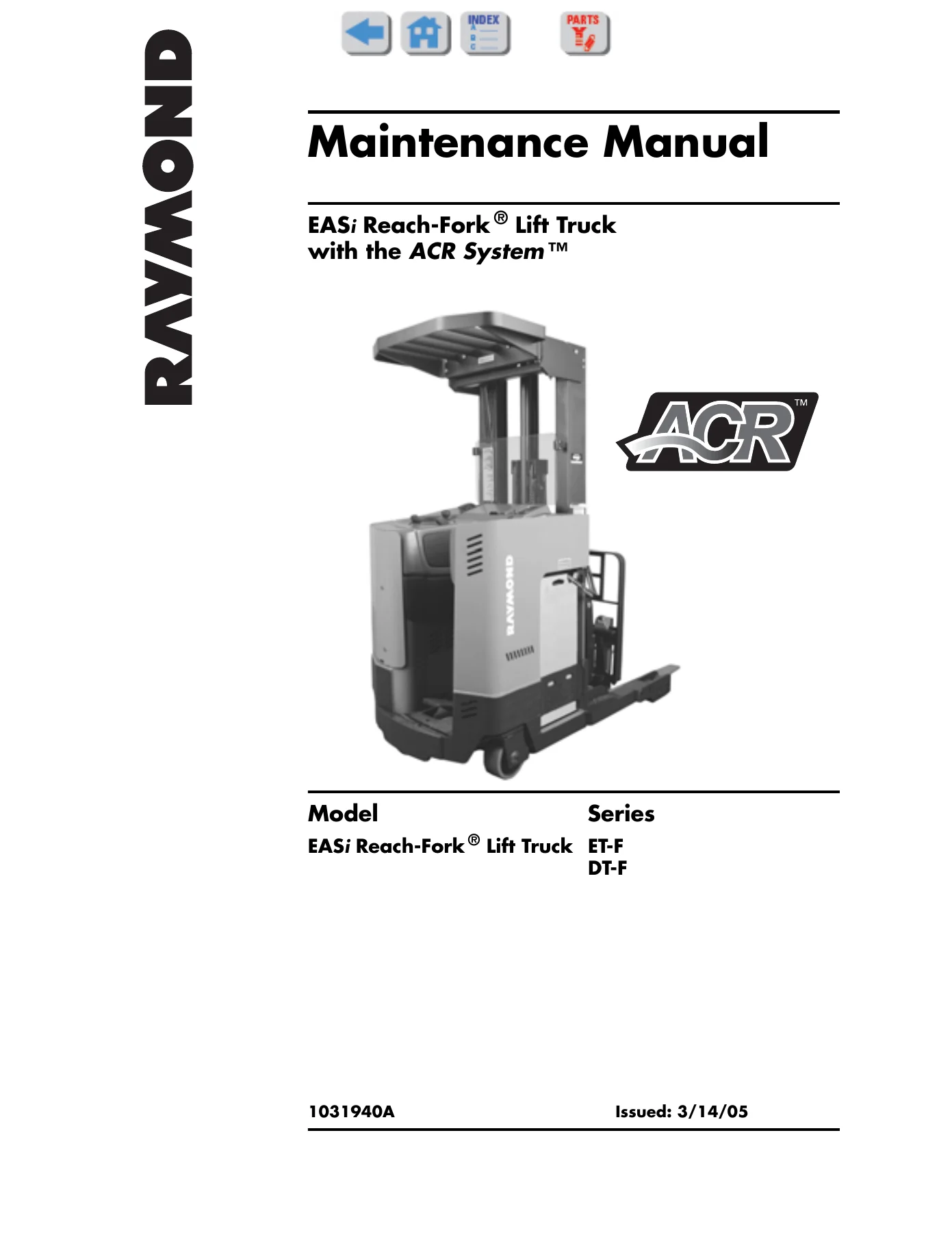
Raymond EASi Reach-Fork ET-F DT-F Maintenance Manual 1031940A

Original price was: $39.95.Current price is: $24.95.

Complete Raymond EASi Reach-Fork ET-F/DT-F maintenance manual, document 1031940A. Covers scheduled maintenance, troubleshooting, fault codes, electrical tests, component procedures, hydraulic systems, and ACR System theory for ET-F and DT-F lift trucks.

⚡
Instant PDF Download
Available immediately
💾
Save to Your Device
Download & keep forever
🛡️
Antivirus Scanned
100% virus-free
🌍
Trusted Worldwide
175,000+ customers

Description

Raymond EASi Reach-Fork ET-F DT-F Maintenance Manual 1031940A

This is the complete Raymond EASi Reach-Fork ET-F/DT-F Maintenance Manual, document number 1031940A. It covers the EASi Reach-Fork Lift Truck with the ACR System, including the ET-F and DT-F model series. This 465-page workshop manual gives technicians and service personnel the full scope of scheduled maintenance, troubleshooting, electrical diagnostics, component procedures, and system theory needed to keep these electric reach trucks running correctly.

File Details

  • Manual Type: Maintenance Manual
  • Brand: Raymond
  • Model Series: EASi Reach-Fork ET-F, DT-F
  • System: ACR System
  • Document Number: 1031940A
  • Original Issue Date: 3/14/05
  • Language: English
  • File Format: PDF
  • Page Count: 465 pages

Chapters Covered

  • How to Use This Manual – manual design, abbreviations, symbols, START page navigation
  • Safety – definitions, general safety, battery safety, static precautions, jacking safety, tie-down for transport, welding safety
  • Systems Overview – introduction, lift truck specifications, operator displays, modes of operation
  • Scheduled Maintenance – maintenance guidelines, Maintenance Minder, initial 90 day/250 HD service, every 90 days/250 HD, every 360 days/2000 HD, scheduled maintenance points, motor maintenance, lubrication points, chain maintenance
  • Troubleshooting – electrical guidelines, shorts to frame test, fuses, DC motor troubleshooting, AC motor troubleshooting, battery state-of-charge, hydraulic guidelines, symptom tables for hydraulic functions, travel functions, and electrical symptoms
  • Messages, Codes, and Tests – firmware changes, modes of operation, power amplifier LED diagnostics, electrical codes, electrical connections, circuit card connectors, analog tests, digital input tests, digital output tests
  • Component Procedures – covers and finish, decals, steering and controls, steering shaft and gear, caster assembly, steered idler wheel, operator display, drive and brake, drive unit, drive motor, brake, deadman pedal, inertial dampener, electrical components, battery procedures, wiring and harness connectors, motors, lift motor, temperature sensor, traction power amplifier, hydraulic components, hydraulic fluid replacement, lift pump, auxiliary pump, main manifold, hydraulic solenoid, pressure transducer, lift cylinders, reach cylinder, tilt cylinder, sideshift cylinder, mast, chain, hose and cable, over-the-mast hose/cable, mast bearing shimming, reach carriage bearings, forks, equalization chains, fork carriage tilt pins, mast backlash adjustment, options, cold storage, fork height-tilt indicator
  • Theory of Operation – traction system functional operation, battery plugged in, turning key switch on, deadman depressed, travel request, proportional plugging, thermal cut-back, steering system, lift/aux system functional operation, lift, lower, reach, sideshift, fork tilt, pinout matrix
  • Appendix – lubrication specification chart, thread adhesives, sealants and lubricants, quick reference torque chart, torque charts for hydraulic fittings, standard and metric ferrous and brass fasteners, decimal equivalent chart, standard/metric conversions, electrical schematics, hydraulic schematic
  • Index – alphabetical subject listing

Complete PDF Bookmark Tree

Complete Bookmarks

The complete bookmarks in the “Raymond EASi Reach-Fork ET-F DT-F Maintenance Manual 1031940A” are as follows:

Cover Pagep. 1
Table of Contentsp. 3
Page Revision Recordp. 7
Section 1. How to Use This Manualp. 9
Map of the Manualp. 10
Design of the Manualp. 11
Abbreviations & Symbolsp. 12
START Pagep. 15
Section 2. Safetyp. 17
Definitionsp. 18
General Safetyp. 19
Battery Safetyp. 22
Static Precautionsp. 25
Figure 2-1. ESD Ground Jack Locationp. 25
Figure 2-2. Anti-Static Kit with Wrist Strap and Matp. 26
Jacking Safetyp. 27
Figure 2-3. A-frame Down-Travel Adjustment Boltp. 27
Figure 2-4. Correct Jacking Locationsp. 27
Tie-Down for Transportp. 28
Welding Safetyp. 29
Section 3. Systems Overviewp. 31
Introductionp. 32
Lift Truck Specificationsp. 33
Figure 3-1. Lift Truck Specification Platep. 33
Battery Specificationsp. 34
Battery Movementp. 34
Mast Typesp. 34
Operator Displaysp. 35
Main Operator Displayp. 35
Figure 3-2. Operator Display, Series ETp. 35
Modes of Operationp. 36
Overview of Modesp. 36
Section 4. Scheduled Maintenancep. 37
Maintenance Guidelinesp. 38
Maintenance Minder ™p. 39
Configurationp. 39
Initial 90 Day/250 Deadman Hours (HD) Maintenancep. 41
Every 90 Days or 250 Deadman Hours (HD)p. 42
Every 360 Days or 2000 Deadman Hours (HD)p. 47
Scheduled Maintenance Pointsp. 48
Figure 4-1. Scheduled Maintenance Points, Mast Viewp. 48
Figure 4-2. Scheduled Maintenance Points, Tractor View (ET Series shown)p. 49
Figure 4-3. Scheduled Maintenance Points, Undersidep. 50
Motor Maintenancep. 51
Motor Cleaningp. 51
Figure 4-4. Motor Cleaning With Compressed Airp. 51
Lubrication Pointsp. 52
Lubrication Point Locator Photosp. 52
Figure 4-5. Lubrication Points, Steering Linkage and A-frame (underside view)p. 52
Figure 4-6. Lubrication Points, Steering Linkage and A-frame (top views)p. 53
Figure 4-7. Lubrication Points, Caster/Idler Wheel Bearing and Axlep. 53
Figure 4-8. Lubrication Points, Steering Shaft/Drive Unitp. 54
Figure 4-9. Reach Assembly (Deep-Reach® lift truck shown)p. 54
Figure 4-10. Reach Mechanismp. 54
Figure 4-11. Lubrication Points, Reach Cylinderp. 55
Figure 4-12. Lubrication Points, Mast and Carriagep. 56
Figure 4-13. Lubrication Points, Reach Mechanism; Sideshift Carriagep. 56
Chain Maintenancep. 57
Section 5. Troubleshootingp. 59
How to Use This Chapterp. 60
Electrical Troubleshooting Guidelinesp. 61
Shorts to Frame Testp. 62
Fusesp. 64
DC Motor Troubleshootingp. 65
Figure 5-1. Motor Circuitsp. 65
AC Motor Troubleshootingp. 69
Figure 5-2. Drive Motor Circuitsp. 69
Battery State-of-Chargep. 70
Theoryp. 70
Setting Battery State-of-Charge Cutoutp. 71
Hydraulic Troubleshooting Guidelinesp. 72
Troubleshooting Procedurep. 73
TS1: START TROUBLESHOOTINGp. 73
GEN1: General Troubleshootingp. 74
END 1: End of Troubleshooting Procedurep. 75
Symptom Tables: Hydraulic Functionsp. 76
Auxiliary Functionsp. 76
Lift/Lower Systemp. 79
Symptom Tables: Travel Functionsp. 81
Slow or Sluggish Accelerationp. 81
Slow Travelp. 82
Symptom Tables: Electrical Symptomsp. 83
Motor Overheatingp. 83
Scrambled or Intermittent Operator Displayp. 84
Dead Lift Truck: Display is Dark; Lift Truck is not Operationalp. 84
Section 6. Messages, Codes, and Testsp. 85
Messages and Codes Summary Listp. 97
Code 1H – Traction Power Amplifier Overheated 6-17p. 97
Code 1T – Battery Low 6-18p. 97
Code 2A – Traction Motor Overheated 6-19p. 97
Code 2C – Traction Power Amplifier Temperature Sensor Out-of-Range 6-20p. 97
Code 2E – Traction Motor Temperature Sensor Out-of-Range 6-21p. 97
Code 2G – Traction Power Amplifier Open Phase or Motor Cable Open 6-22p. 97
Code 2H – Failure Detected in Traction Motor Feedback Encoder 6-23p. 97
Code 2M – Traction Power Amplifier Precharge Failed 6-24p. 97
Code 2T – Traction Power Amplifier Current Sensor Fault 6-25p. 97
Code 2U – Traction Power Amplifier Overcurrent or Short Circuit 6-26p. 97
Code 2V – Traction Power Amplifier High DC Voltage 6-27p. 97
Code 2W – Traction Power Amplifier Internal Fault 6-28p. 97
Code 2X – Traction Power Amplifier Power Supply Out-of-Range 6-29p. 97
Code 42 – Lift Contactor Detected Closed When Commanded Open 6-30p. 97
Code 43 – Lift Contactor Detected Open When Commanded Closed 6-31p. 97
Code 44 – PC Contactor Detected Closed When Commanded Open 6-32p. 97
Code 45 – PC Contactor Detected Open When Commanded Closed 6-33p. 97
Code 4F – TPC Detected Closed When Commanded Open 6-34p. 97
Code 4G – TPC Detected Open When Commanded Closed 6-35p. 97
Code 4H – TPC Coil Driver Fault 6-36p. 97
Code 59 – CAN Transmission Buffer Error 6-37p. 97
Code 5G – No Communications Received from Traction Power Amplifier 6-38p. 97
Code 6D – Pressure Sensor Out-of-Range 6-39p. 97
Code 80 – Throttle Potentiometer Out-of-Range 6-40p. 97
Code 81 – Lift Potentiometer Out-of-Range 6-41p. 97
Code 83 – Traction Potentiometer Out-of-Neutral 6-42p. 97
Code 84 – Brake Inoperable 6-43p. 97
Code 8F – Lift Potentiometer Out-of-Neutral 6-44p. 97
Code 8N – Optional Auxiliary Start Switch Closed at Start-Up 6-45p. 97
Code AG – Communications To/From Operator Display Failed 6-46p. 97
Code AH – Bad Operator Display Checksum 6-47p. 97
Code AJ – Bad VM ROM Memory 6-48p. 97
Code AK – Bad VM RAM Memory 6-49p. 97
Code AL – Bad Battery Backed-Up VM RAM Memory 6-50p. 97
Code AO – Incorrect Software For Correct Lift Truck Operation 6-51p. 97
Code AP – Traction Power Amplifier Software Fault 6-52p. 97
Code E1 – HTI Encoder Channel Failed 6-53p. 97
Code E2 – HTI Encoder Failed 6-54p. 97
Code EC – Vehicle Manager Operating System Error 6-55p. 97
Code FG – 12V Power Supply Out-of-Range 6-56p. 97
Code FH – Battery Voltage Out-of-Range 6-57p. 97
Power Amplifier LED Diagnosticsp. 99
Figure 6-1. Power Amplifier Status Indicator LEDp. 99
Electrical Codesp. 100
Electrical Connectionsp. 143
Figure 6-2. Molex Jack and Pin Connectorp. 143
Circuit Card Connectorsp. 144
Figure 6-3. Vehicle Manager Connectorsp. 144
Figure 6-4. Relay/Control Fuse Panel connectorsp. 145
Electrical Test Summary Listp. 147
Analog Testsp. 149
Digital Input Testsp. 161
Digital Output Testsp. 181
Firmware Changesp. 86
Vehicle Managerp. 86
Power Amplifierp. 86
Modes of Operationp. 87
Overview of Modesp. 87
Run Mode Tonesp. 88
Entering Program Modep. 88
Entering a Password or Superwordp. 88
Using Configure Modep. 89
Configure Mode Settingsp. 91
Using Learn Modep. 93
Using Maintenance Modep. 94
Section 7. Component Proceduresp. 199
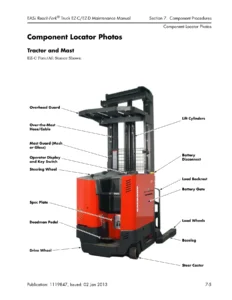
Component Locator Photosp. 201
Figure 7-1. Mast and Tractor, ET Seriesp. 201
Figure 7-2. Mast and Tractor, ET Series (covers removed)p. 202
Figure 7-3. Tractor, ET Seriesp. 203
Figure 7-4. Tractor, DT Seriesp. 204
Figure 7-5. Carriagep. 205
Figure 7-6. Underside Components (with optional Steered Idler)p. 206
Figure 7-7. Contactor/Fuse Panel Layoutp. 207
Covers and Finishp. 209
Decalsp. 210
Figure 7-8. Decal and Specification Plate Locations, Tractorp. 211
Figure 7-9. Warning Decalsp. 212
Steering and Controlsp. 213
Steering Shaft and Gearp. 214
Removalp. 214
Figure 7-10. Steering Shaftp. 214
Installationp. 214
Figure 7-11. Steering Shaft and Gear Assemblyp. 215
Figure 7-12. Steering Shaft Bearingp. 215
Caster Assemblyp. 216
Removalp. 216
Installationp. 216
Steered Idler Wheel (optional)p. 217
Figure 7-13. Setting Drive Wheel Parallelp. 217
Figure 7-14. Steering Adjustmentsp. 217
Figure 7-15. Cover Platep. 218
Figure 7-16. A-frame Down-Travel Adjustment Boltp. 218
Figure 7-17. A-frame Spring adjustmentsp. 218
Figure 7-18. A-frame Up-Travel Stop Adjustmentp. 219
Figure 7-19. Steering Linkage Exploded Viewp. 220
Operator Display (OD)p. 221
Figure 7-20. Operator Display Interface Card (ET Series)p. 221
Figure 7-21. Operator Display Interface Card (DT Series)p. 221
Drive and Brakep. 223
Drive Unitp. 224
Inspectionp. 224
Figure 7-22: Placement of Dial Indicatorp. 224
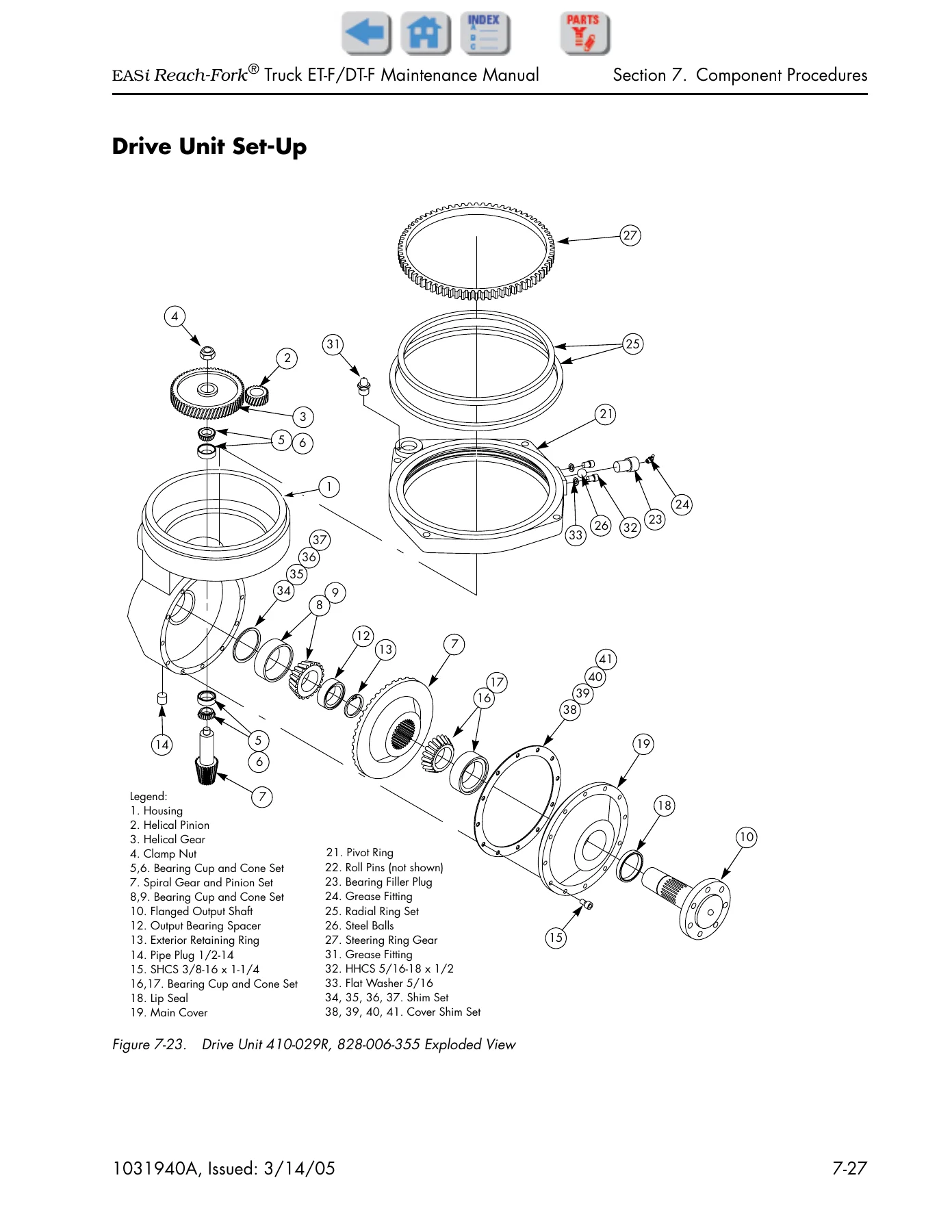
Drive Unit Set-Upp. 225
Figure 7-23. Drive Unit 410-029R, 828-006-355 Exploded Viewp. 225
Figure 7-24. Drive Unit Removal/Installation Toolp. 226
Removalp. 226
Disassemblyp. 227
Figure 7-25. Remove Grease Fitting and Filler Plugp. 227
Figure 7-26. Remove Steel Ball Bearingsp. 227
Figure 7-27. Remove Pivot Ringp. 228
Figure 7-28. Remove Radial Ringsp. 228
Figure 7-29. Remove Cover and Output Shaftp. 228
Figure 7-30. Press Down Output Shaftp. 229
Figure 7-31. Press Out Output Shaftp. 229
Figure 7-32. Remove Bevel Gearp. 229
Figure 7-33. Remove Bearing Cup and Lip Sealp. 229
Figure 7-34. Remove Output Shaft Bearing Conep. 230
Figure 7-35. Remove Clamp Nutp. 230
Figure 7-36. Remove Spiral Pinionp. 230
Figure 7-37. Remove Bearing Cupp. 230
Assemblyp. 231
Figure 7-38. Drive In Bearing Cupp. 231
Figure 7-39. Press Bearing onto Spiral Pinionp. 231
Figure 7-40. Press Lip Sealp. 231
Figure 7-41. Press Output Bearing Cupp. 232
Figure 7-42. Bearing Cone to Flange Measurementp. 232
Figure 7-43. Install Main Cover and Bearing Conep. 232
Figure 7-44. Press on Bearing Conep. 232
Figure 7-45. Press on Bevel Gearp. 233
Figure 7-46. Press Down Bearing Conep. 233
Figure 7-47. Eliminate Backlashp. 233
Figure 7-48. Bearing Cup to Flange Measurementp. 233
Figure 7-49. Install Helical Gear and Pinionp. 234
Figure 7-50. Bearing Cone to Flange Measurementp. 234
Figure 7-51. Bearing Cup to Flange Measurementp. 234
Figure 7-52. Remove End Playp. 235
Figure 7-53. Mark Spiral and Bevel Gearsp. 235
Figure 7-54. Install Cover Shimsp. 235
Figure 7-55. Line Up Spiral and Bevel Gearsp. 235
Figure 7-56. Backlash Measurementp. 236
Figure 7-57. Install Roll Pinsp. 236
Figure 7-58. Install Radial Ringsp. 236
Figure 7-59. Install Outer Radial Ringsp. 237
Figure 7-60. Install Ball Bearingsp. 237
Figure 7-61. Install Bearing Filler Plugp. 237
Installationp. 237
Drive Motorp. 239
Figure 7-62. Cable Routing and Tiesp. 240
Brakep. 241
Figure 7-63. Brake cross-sectionp. 241
Brake Adjustmentp. 242
Figure 7-64. Brake Adjustmentp. 242
Brake Pad Inspectionp. 242
Upper Brake Pad Replacementp. 242
Figure 7-65. Upper Brake Pad Removalp. 242
Figure 7-66. Brake, disassembledp. 243
Figure 7-67. Brake Gap, settingp. 243
Brake Assemblyp. 244
Figure 7-68. Brake Assembly Removalp. 244
Brake O-ring Seal Replacementp. 245
Figure 7-69. Brake, disassembledp. 245
Bleeding Brakep. 245
Deadman (Brake) Pedalp. 247
Inertial Dampener (optional)p. 248
Removalp. 248
Figure 7-70. Cover Platep. 248
Figure 7-71. Inertial Dampener (unrelated parts removed for clarity)p. 248
Figure 7-72. Inertial Dampener (nuts, retainer, springs, friction plate removed)p. 248
Figure 7-73. Inertial Dampener (jacked up for shoulder bolt removal)p. 249
Figure 7-74. Inertial Dampener (A-frame springs, slide plate removed)p. 249
Installation and Adjustmentp. 249
Figure 7-75. Inertial Dampener adjustmentp. 250
Figure 7-76. Inertial Dampener partsp. 250
Electrical Componentsp. 251
Battery Proceduresp. 252
Battery Connector/Cablesp. 252
Figure 7-77. Battery Disconnect Blockp. 252
Figure 7-78. Battery Cable Removal from Connectorp. 252
Figure 7-79. Battery Cable and Connectorp. 253
Battery Rollersp. 253
Figure 7-80. Battery Cable and Filler Plugp. 253
Battery Exterior Cleaningp. 253
Testing, Charging, and Maintenancep. 254
Wiring and Harness Connectorsp. 255
General Repair Proceduresp. 255
Molex Connectorsp. 256
Figure 7-81. Molex Connector, end viewp. 256
Figure 7-82. Pin Extractionp. 256
AMP Harness/Harness Connectorsp. 257
Figure 7-83. AMP Water-Resistant Connectorp. 257
Figure 7-84. AMP pin extractionp. 257
Figure 7-85. Removing wirep. 258
Figure 7-86. Wire Sealp. 258
Figure 7-87. Wire insertionp. 258
Figure 7-88. Sealing Plugp. 258
Figure 7-89. Interface Sealp. 259
Figure 7-90. Latching AMP connectorp. 259
AMP Harness/Traction Power Amplifier Connectorp. 260
Figure 7-91. JPT1 Connector Componentsp. 260
Figure 7-92. AMP JPT1 Connectorp. 260
Figure 7-93. Contact Insertionp. 261
Figure 7-94. Wedge Lock Latchesp. 261
Figure 7-95. Wedge Lock Flush With Housingp. 262
Motorsp. 263
DC Motor Brushesp. 263
Figure 7-96. Motor Brush, Typical Locationp. 263
DC Motor Brush Spring Tensionp. 264
Figure 7-97. Motor Brush Spring Tension Inspectionp. 264
DC Motor Commutatorp. 265
Figure 7-98. Mica Undercuttingp. 265
Terminal Hardwarep. 265
Figure 7-99. Terminal Nutsp. 266
Figure 7-100. Two wrenches on motor terminalsp. 266
Lift Motorp. 267
Removalp. 267
Figure 7-101. Lift Motor, ET Seriesp. 267
Installationp. 267
Temperature Sensor, Tractionp. 269
Installation (External)p. 269
Figure 7-102. Drive Motor External Temperature Sensorp. 269
Traction Power Amplifierp. 270
Removalp. 270
Figure 7-103. Traction Power Amplifierp. 270
Installationp. 270
Hydraulic Componentsp. 271
Hydraulic Fluid Replacementp. 272
Preparationp. 272
Purging the Auxiliary Systemp. 272
Purging the Steering Systemp. 273
Purging the Lift Cylindersp. 273
Refilling the Systemp. 273
Bleeding the Systemp. 273
Figure 7-104. Bleed Screw, Side Lift Cylinderp. 273
Lift Pumpp. 275
Figure 7-105. Lift Pump Location (ET Series shown)p. 275
Installationp. 275
Figure 7-106. Lift Motor and Pump Splinep. 275
Lift Pressure Adjustmentp. 276
Figure 7-107. Lift Pressure Adjustmentp. 276
Manual Lowering of Fork Carriagep. 277
Figure 7-108. Lift Pressure Relief Valve & Adjusting Screwp. 277
Proportional Lower Valve Adjustmentp. 278
Figure 7-109. Proportional Lower Valvep. 278
Auxiliary Pumpp. 279
Installationp. 279
Figure 7-110. Auxiliary Pump with Couplingp. 279
Figure 7-111. AUX Motor and Pump (ET Series)p. 279
Auxiliary System Pressure Adjustmentp. 280
Figure 7-112. Auxiliary Pressure Test Port, ET Series shownp. 280
Figure 7-113. Aux Pressure Adjustment Screw, DT Seriesp. 280
Manifold, Mainp. 281
Figure 7-114. Manifold Layout, Top View (Dual Lift Pump shown)p. 281
Figure 7-115. Manifold Layout, Side View (Dual Lift Pump shown)p. 281
Hydraulic Solenoidp. 282
Installationp. 282
Figure 7-116. Solenoid, Typical, Coil Removedp. 282
Pressure Transducerp. 283
Installationp. 283
Figure 7-117. Pressure Transducerp. 283
Hydraulic Componentsp. 285
Lift Cylindersp. 285
Figure 7-118. Lift Cylinder, Back Cylinder, exploded viewp. 286
Figure 7-119. Lift Cylinder, Front Cluster, exploded view (Part 1 of 2)p. 287
Figure 7-120. Lift Cylinder, Front Cluster, exploded view (Part 2 of 2)p. 288
Lift Cylinder, Front Clusterp. 289
Figure 7-121. Front Ram Top Mountingp. 289
Lift Cylinder, Back Cylinder, Threaded Anchor Retentionp. 290
Figure 7-122. Reach carriage removedp. 290
Figure 7-123. Anchoring lift cylinderp. 291
Figure 7-124. Blocking telescopicsp. 292
Figure 7-125. Checking pivot support platep. 292
Figure 7-126. Blocking inner telescopicp. 292
Lift Cylinder, Side Cylinder Seal Repackingp. 293
Figure 7-127. Cylinder Seal Installation Guide & Driverp. 293
Lift Cylinder, Front and Back Cylinder Seal Repackingp. 294
Figure 7-128. Cylinder Seal Installation Guide & Driverp. 294
Lift Cylinder Lowering Cushionp. 295
Flow Controlp. 296
Removalp. 296
Figure 7-129. Flow Control, Blockingp. 296
Installationp. 296
Reach Cylinderp. 298
Adjustmentp. 298
Figure 7-130. Blocking Carriagep. 298
Removalp. 298
Figure 7-131. Reach Cylinder Hydraulic Hosesp. 298
Figure 7-132. Reach Cylinder Yoke Attachmentp. 298
Figure 7-133. Reach Cylinder Housing Attachmentp. 299
Disassemblyp. 299
Figure 7-134. Removing External Lock Ringp. 299
Figure 7-135. Reach Cylinder Disassemblyp. 300
Reassemblyp. 300
Figure 7-136. Deep-Reach® Cylinder Disassemblyp. 301
Installationp. 301
Tilt Cylinderp. 302
Seal Replacementp. 302
Figure 7-137. Tilt Cylinder, Disassemblyp. 302
Sideshift Cylinderp. 304
Removalp. 304
Installationp. 304
Seal Replacementp. 304
Figure 7-138. Bolzoni Sideshift Assemblyp. 305
Mast, Chain, Hose and Cablep. 307
Over-the-Mast Hose/Cablep. 308
Removalp. 308
Figure 7-139. Blocking Inner and Outer Telescopicsp. 308
Figure 7-140. Over-the-Mast Hose/Cable Retaining Screwsp. 308
Figure 7-141. Over-the-Mast Hose connections (reach)p. 308
Installationp. 309
Adjustmentp. 309
Figure 7-142. Hose and Cable Tension Adjustmentp. 310
Mast Bearing Shimmingp. 311
Figure 7-143. Blocking Mastp. 311
Figure 7-144. Upper Mast Bearing, Outer Telescopicp. 312
Figure 7-145. Upper Mast Bearing, Main Mastp. 312
Complete Mast Shimmingp. 312
Figure 7-146. Mast Disassembly, securing hoses/cablep. 313
Figure 7-147. Shimming Outer Telescopic Bearingp. 314
Figure 7-148. Shimming Inner Telescopic Bearingp. 315
Bearings, Reach Carriagep. 318
Removalp. 318
Figure 7-149. Reach Carriage Roller Bearingsp. 318
Installationp. 318
Bearings, Reach Half Shaftp. 319
Removalp. 319
Figure 7-150. Half Shaft Locationp. 319
Installationp. 319
Figure 7-151. Half Shaft Assemblyp. 319
Reach Carriage Assemblyp. 320
Removalp. 320
Figure 7-152. Blocking Reach Mechanism and Forksp. 320
Figure 7-153. Carriage Removal, Hoses, Cable, & Chainsp. 320
Figure 7-154. Carriage Removedp. 321
Installationp. 321
Forksp. 322
Fork Inspectionp. 322
Figure 7-155. Fork Wear Calipersp. 322
Figure 7-156. Fork Wear Inspectionp. 322
Equalization Chainsp. 323
Adjustmentp. 323
Figure 7-157. Equalization Chain Adjustmentp. 323
Lubricationp. 323
Removalp. 323
Figure 7-158. Blocking Inner and Outer Telescopicsp. 324
Figure 7-159. Equalization Chain Adjuster Lock Nutp. 324
Figure 7-160. Equalization Chain Anchor Cap Screwsp. 324
Installationp. 324
Fork Carriage Tilt Pinsp. 326
Removalp. 326
Figure 7-161. Fork Carriage Tilt Pinp. 326
Figure 7-162. Removing Tilt Pivot Pinp. 326
Installationp. 326
Mast Backlash Adjustmentp. 327
Figure 7-163. Mast Backlash Bolt locationp. 327
Optionsp. 329
Cold Storagep. 330
Componentsp. 330
Lubricantsp. 330
Sealing Treatmentp. 330
Corrosion Inhibitor Coatingp. 330
Fork Height-Tilt Indicator (HTI)p. 331
Fork Height Indicatorp. 331
Fork Tilt Indicatorp. 331
Codes and Troubleshootingp. 331
HTI Active Maintenance Modep. 331
Figure 7-164. HTI Displayp. 331
Figure 7-165. HTI Active Maintenance Mode segmentsp. 332
Fork Height Indicatorp. 333
Figure 7-166. HTI Cable attachment (top)p. 333
Figure 7-167. HTI Cable attachment (bottom)p. 333
Figure 7-168. HTI Encoder Cable Pathp. 334
Figure 7-169. HTI Encoder Assembly Installationp. 334
Figure 7-170. HTI Encoder Assemblyp. 335
Figure 7-171. HTI Display Cardp. 335
Figure 7-172. HTI Displayp. 336
Fork Tilt Indicatorp. 336
Figure 7-173. Tilt Plates and Shims (one side visible)p. 336
Figure 7-174. HTI Pressure Switchp. 337
HTI Theory of Operationp. 337
Section 8. Theory of Operationp. 339
Traction System Functional Operationp. 340
Battery Plugged Inp. 340
Figure 8-1. Battery Plugged Inp. 342
Turning Key Switch (S1) ONp. 344
Figure 8-2. Turning Key Switch (S1) ONp. 346
Startup Sequencep. 348
SelfTest Checksp. 348
Deadman Depressed (S2)p. 348
Figure 8-3. Deadman (S2) Depressedp. 350
Travel Requestp. 353
Figure 8-4. Travel Requestp. 354
Proportional Pluggingp. 357
Figure 8-5. Pluggingp. 358
Thermal Cut-Backp. 360
Steering Systemp. 361
Steering Processp. 361
Figure 8-6. Steering Theory – Hydraulicp. 361
Figure 8-7. Steering Theory – Electricalp. 362
Lift/Aux System Functional Operationp. 364
System Componentsp. 364
Theory of Functionp. 366
Liftp. 366
Figure 8-8. Pulse Width Modulation duty cyclep. 366
Figure 8-9. Lift – Hydraulicp. 367
Figure 8-10. Lift – Electricalp. 368
Lowerp. 370
Figure 8-11. Pulse Width Modulation duty cyclep. 370
Figure 8-12. Lower – Hydraulicp. 371
Figure 8-13. Lower – Electricalp. 372
Reachp. 374
Figure 8-14. Slow Speed Reach – Electricalp. 376
Figure 8-15. Slow Speed Reach – Hydraulicp. 378
Figure 8-16. High Speed Reach – Hydraulicp. 379
Figure 8-17. High Speed Reach – Electricalp. 380
Sideshiftp. 382
Figure 8-18. Sideshift – Hydraulicp. 383
Figure 8-19. Sideshift – Electricalp. 384
Fork Tiltp. 386
Figure 8-20. Hydraulic Schematic – Fork Tiltp. 387
Figure 8-21. Electrical Schematic – Fork Tiltp. 388
Pinout Matrixp. 391
Section A. Appendixp. 405
Lubrication Specification Chartp. 406
Thread Adhesives, Sealants, and Lubricantsp. 407
Quick Reference Torque Chartp. 408
Torque Chart – Hydraulic Fittingsp. 409
Torque Chart – Straight Thread Face Seal O-Ringsp. 409
Torque Chart – Standard (Ferrous)p. 410
Torque Chart – Metric (Ferrous)p. 411
Torque Chart – Metric (Brass)p. 411
Torque Chart – Standard (Brass)p. 412
Decimal Equivalent Chartp. 413
Standard/Metric Conversionsp. 415
Electrical Schematicsp. 417
Figure A-1. Electrical Schematic, Sheet 1p. 418
Figure A-2. Electrical Schematic, Sheet 2 (Options)p. 420
Figure A-3. Electrical Schematic Legendp. 422
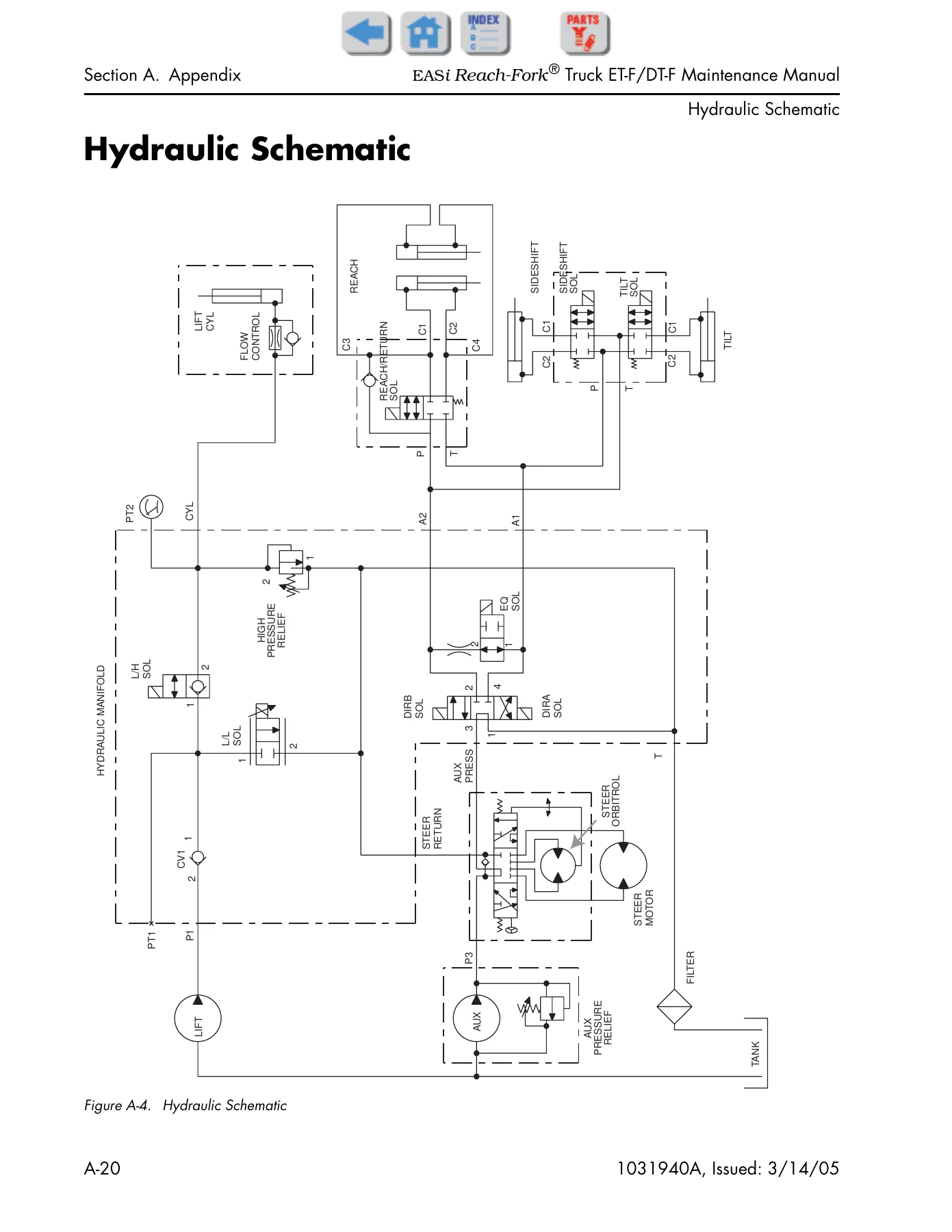
Hydraulic Schematicp. 424
Figure A-4. Hydraulic Schematicp. 424
Section I. Indexp. 425
RSIsp. 437
Recommended Lift Chain Lubricationp. 437
New Traction Motor Compartment Door Latchp. 438
New Software Releasep. 439
Drive Unit Updatesp. 440
New Software Releasesp. 441
Intermittent 2T Codesp. 442
Reach Cylinder Adjustment Procedurep. 443
Shorts to Frame Testp. 444
Static Strap Resistancep. 445
Configuration Code Changesp. 446
Drive Motor Pinion Nutp. 447
Terminal Torque on Curtis Power Amplifier P/N 1042226/XXXp. 449
Warning Light Failuresp. 450
New Firmware Version 1.7p. 452
Code 58 & Code 59 issuesp. 453
Terminal Stud Rotation on Curtis Motor Controllersp. 454
Servicing of Power Cables Used on AC Motorsp. 455
Updated Scheduled Maintenance Suggested Intervalsp. 459
Operator Compartment Sensor System (OCSS)p. 461
Amplifier Cable Routingp. 463
Power Amplifier Cooling Fan(s)p. 465

What This Manual Covers

The Raymond EASi Reach-Fork ET-F/DT-F Maintenance Manual is built for anyone responsible for the upkeep, diagnosis, and repair of these electric reach trucks. It opens with safety procedures covering battery handling, jacking, welding, and static precautions. The scheduled maintenance chapter lays out service intervals based on deadman hours, covering everything from lubrication points to chain inspection and motor cleaning. The troubleshooting chapter provides symptom tables for hydraulic, travel, and electrical problems, along with the shorts-to-frame test procedure and detailed DC and AC motor diagnostics. The messages, codes, and tests chapter is a deep reference for fault codes, power amplifier LED diagnostics, and electrical tests for every circuit on the truck. The component procedures chapter walks through removal, installation, disassembly, and adjustment for steering, drive, brake, electrical, hydraulic, mast, and carriage components. The theory of operation chapter explains how the traction, steering, and lift/auxiliary systems work, with schematics and a full pinout matrix. The appendix supplies torque charts, lubrication specs, conversion tables, and electrical and hydraulic schematics.

Who This Manual Is For

This manual is written for trained technicians, service managers, and maintenance personnel working on Raymond EASi Reach-Fork ET-F and DT-F lift trucks. It assumes you have read the Owner/Operator Manual and have the training and authorization to work on the truck. The procedures are detailed enough for component-level repair and system-level troubleshooting, with torque values, pressure settings, and test procedures throughout. The theory of operation chapter is especially useful when diagnosing intermittent faults or understanding how the ACR System controls traction, steering, and hydraulic functions. The electrical codes section lists fault codes with system responses, performance limits, and the tests to run for each code, making it a practical diagnostic companion.

Why This Manual Matters

Working on a reach truck without the correct procedures and specifications can lead to misdiagnosed faults, damaged components, or unsafe operating conditions. This manual provides the manufacturer’s procedures for scheduled maintenance, the correct torque values for fasteners, the pressure settings for hydraulic systems, and the test procedures for electrical circuits. It covers the ACR System, which uses a brushless AC traction motor, a traction power amplifier, a vehicle manager, and CAN bus communications – systems that require specific diagnostic approaches. The battery state-of-charge feature, maintenance minder, and operator display settings are also covered, so you can configure and troubleshoot the truck’s electronic systems correctly. Whether you are performing a 90-day service, tracking down a fault code, or rebuilding a drive unit, this manual has the procedure and the specifications you need.

Get Instant Access

The Raymond EASi Reach-Fork ET-F/DT-F Maintenance Manual 1031940A is delivered as a PDF file, available for immediate download after purchase. There is no shipping, no waiting for a physical book, and no risk of a damaged or lost copy. You can view it on any device – laptop, tablet, or smartphone – and print the pages you need for the shop floor. The searchable text lets you jump to the section or fault code you need. Keep it on your service truck, in the maintenance office, or on your phone for quick reference during repairs.

IMAGES PREVIEW
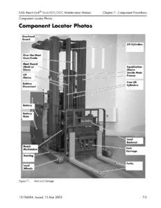
Raymond EASi Reach-Fork ET-F DT-F Maintenance Manual 1031940A — PDF page 1 preview
Raymond EASi Reach-Fork ET-F DT-F Maintenance Manual 1031940A — PDF page 225 preview
Raymond EASi Reach-Fork ET-F DT-F Maintenance Manual 1031940A — PDF page 424 preview

Reviews

There are no reviews yet.

Be the first to review “Raymond EASi Reach-Fork ET-F DT-F Maintenance Manual 1031940A”

What Our Customers Say

★★★★★ Live reviews from customers
Loading customer reviews...
0
    0
    Your Cart
    Your cart is emptyReturn to Shop
    🛒
    Recently Purchased
    🕒 verified order