
Samsung RS80A Ultrasound Service Manual Version 2.00 PDF Repair Guide
Original price was: $39.95.$24.95Current price is: $24.95.
Service manual for the Samsung Medison RS80A ultrasound system, Version 2.00, covering installation, system structure, service mode, troubleshooting, disassembly, probes, maintenance, and service parts.
Description
Samsung RS80A Ultrasound Service Manual Version 2.00 PDF Repair Guide
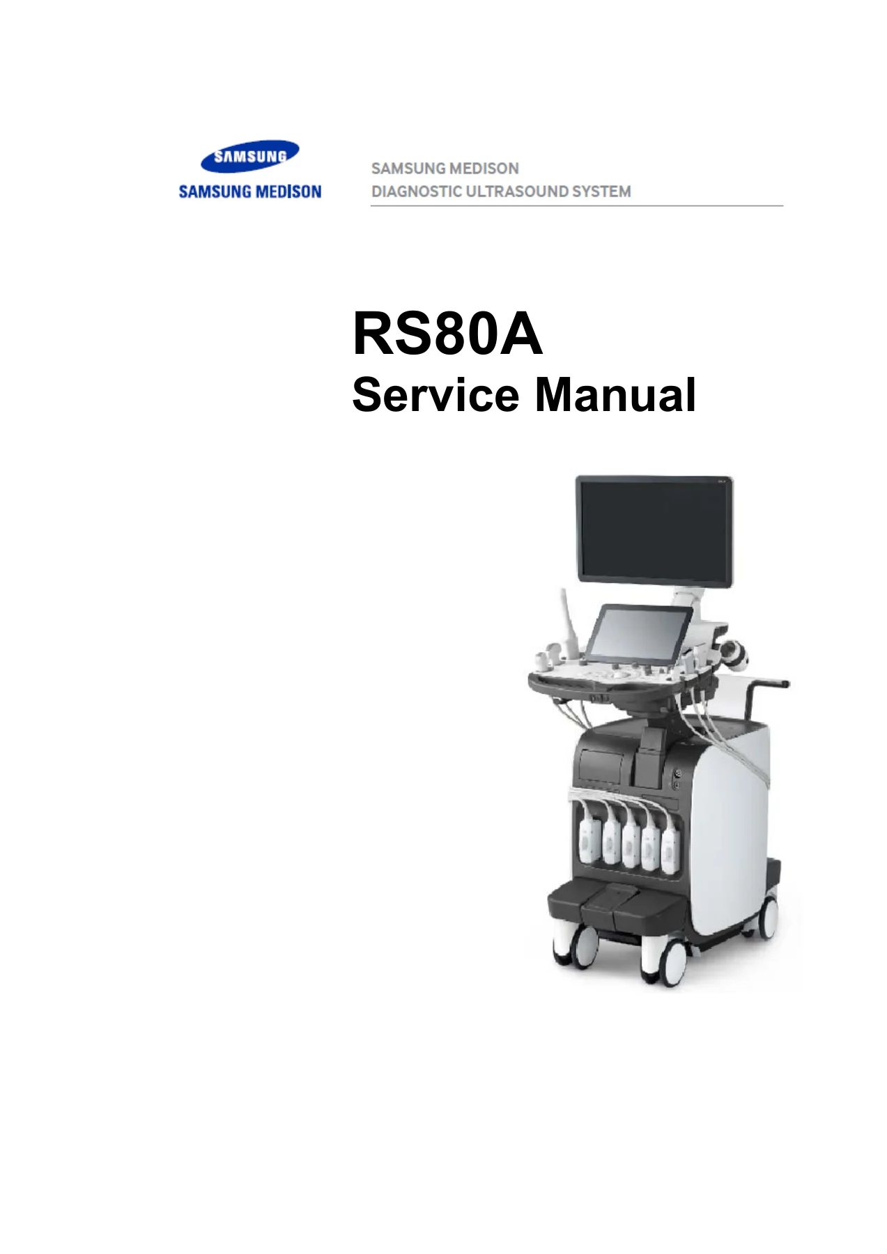
The Samsung RS80A Ultrasound Service Manual Version 2.00 PDF Repair Guide is a service-oriented document for the RS80A Diagnostic Ultrasound System. It is written for service and technical support work on the system, its probes, and related assemblies. The manual identifies the product as the RS80A and covers Version 2.00, with document code SM-RS80A-ENG-01 and an initial release date of 2015.05.28. It is an English-language PDF service manual with 297 pages and 11 chapters, ranging from safety and installation through troubleshooting, disassembly, probe care, maintenance, and service parts.
The document is practical rather than clinical: it states that it does not include diagnosis results or opinions. Its value is in showing how the RS80A system is configured, how major assemblies are arranged, how service mode and admin functions are accessed, and how common power, monitor, boot, and image problems are approached. It also includes detailed disassembly and assembly procedures for major modules and a service parts list with part codes and names.
File Details
- Manual type: Service Manual
- Brand: Samsung Medison
- Model: RS80A Diagnostic Ultrasound System
- Document title: RS80A Service Manual
- Version: 2.00
- Document code: SM-RS80A-ENG-01
- Revision shown: v2.00.00-00
- Initial release date: 2015.05.28
- Language: English
- Page count: 297
- File format: PDF
Chapters Covered
- Chapter 1 Introduction
- Specifications
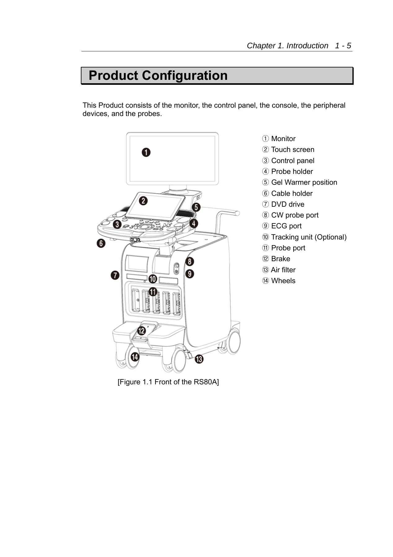
- Product Configuration
- Monitor
- Control Panel
- Console
- Peripheral Devices
- Probes
- Accessories
- Optional Functions
- Chapter 2 Safety
- Purpose of Use
- Contraindications
- Safety Information and Symbols
- Electrical Safety
- ECG-Related Information
- ESD and EMI
- EMC
- Mechanical Safety
- Biological Safety and ALARA Principle
- Environmental Protection
- Chapter 3 Installing the Product
- Transporting
- Unpacking the Product
- Installation Environment
- Installing the Product
- System Power
- System Settings
- System General Setting
- Scan Mode
- Display
- Annotate
- Peripheral Device Settings
- User Defined Keys
- Network
- DICOM Settings
- Options
- System Information
- Chapter 4 Product Inspection
- Basic Inspections
- Detailed Inspections
- Chapter 5 Product Structure
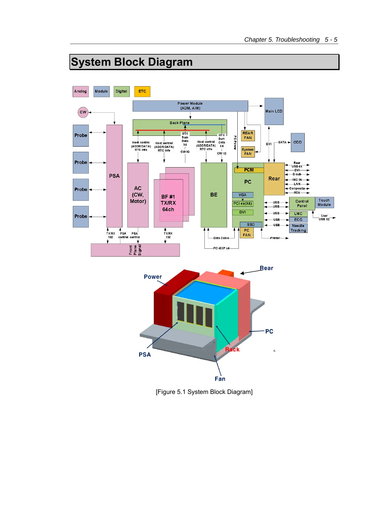
- System Block Diagram
- Basic Structure of the Product
- Ultrasound System Part
- PC Part
- User Interface Part
- Power Part
- PSA, Beam Former Board, Analog Control, Back End Board
- PC Module, PCIE, DVI
- Rear Board
- PTM and LMC
- Control Panel, Monitor, Touch Screen
- Display Layout
- AIM + ADM
- Interconnect Diagram
- Chapter 6 Service Mode
- Prestige Option
- Enter Installation Key
- System Information
- Windows Mode
- Admin Mode
- Adding and Deleting Options
- RMS Control
- Chapter 7 Troubleshooting
- Power Issues
- Power Does Not Turn On
- Power Does Not Turn Off
- Power Turns Off by Itself
- Monitor Problems
- Error Messages
- Image Problems
- 2D Mode Image and Noise Issues
- M, C, PW, CW Mode Trouble
- Error Code Table
- Chapter 8 Disassembly and Assembly
- Caution and Preparation
- Detaching the Board Box
- Detaching the Air Filter and Lower Fan
- Detaching the Rear Module
- Detaching the PC Module
- Detaching the Control Panel
- Detaching the Monitor
- Detaching the Monitor Arm
- Assembling the Product
- Installing Gel Warmer on the Left
- Vaginal Probe Holder
- Chapter 9 Probes
- Probe List and Applications
- Presets and Function List
- Thermal Index Tables
- Ultrasound Transmission Gel
- Using Sheaths
- Probe Precautions
- Cleaning and Disinfecting the Probe
- Chapter 10 Maintenance
- Operating Environment
- System Maintenance
- Cleaning and Disinfection
- Electrical Safety Check
- Accuracy Check
- Data Maintenance
- User Settings Backup
- Patient Information Backup
- Software
- Cybersecurity
- Chapter 11 Service Parts List
- Body Cover Parts
- Monitor and Arm Parts
- Control Panel Parts
- System Parts
- System Cable Parts
Across these chapters, the manual gives a structured view of the RS80A as a serviceable ultrasound system rather than a single-board device. It identifies the main electronic and mechanical sections, explains how the ultrasound system part, PC part, user interface part, and power part relate to one another, and includes block diagrams and interconnect information. The disassembly chapter is organized by major modules, while the parts chapter lists covers, boards, cables, monitor and arm components, control panel parts, and system parts by part code and name. The probe chapter adds application tables, probe handling precautions, approved cleaning and disinfection information, and references for ultrasound gel and sheaths.
Service and Troubleshooting Scope
For technicians, the Samsung RS80A Ultrasound Service Manual Version 2.00 PDF Repair Guide supports work across several practical areas. The troubleshooting chapter begins with power faults: no power on, no power off, and power turning off by itself. It then moves to monitor symptoms such as a blank screen or discoloration, boot-time error messages, 2D image echo or format problems, noise lines, and M, C, PW, and CW mode trouble. The error code table maps codes to locations such as SW, PC, AC Board, BF Board, BE Board, and DVI Board, with estimated failure descriptions.
The service mode chapter is important for configuration and access tasks. It covers the Prestige option for Version 2.00, installation key entry, system information, Windows mode access, Admin mode functions, option add and delete procedures, and RMS control. The admin functions include language selection, test patterns, restore and backup, display information, printer settings, auto freeze timer, video output, region preset, and FPGA memory download. These are service-level operations that are not part of ordinary clinical use.
The product structure chapter gives the technical map. It describes the PSA, beamformer board, analog control board, back end board, PC module, PCIE and DVI boards, rear board, control panel, monitor, touch screen, PTM, LMC, and AIM plus ADM power arrangement. It also includes system block diagrams, board layouts, interconnect diagrams, and display layout information. This is useful when tracing a fault between the ultrasound system part and the PC part, or when checking power distribution, USB paths, video paths, and control panel connections.
The disassembly and assembly chapter is written as a sequence of service procedures. It explains how to detach the board box, air filter and lower fan, rear module, PC module, control panel, monitor, and monitor arm. It also covers assembly, optional gel warmer installation on the left side, and vaginal probe holder installation. The procedures are presented with cautions about high voltage, antistatic protection, and safe handling of the product.
Maintenance, Probes, and Parts Reference
The maintenance chapter covers operating environment limits and system maintenance. It gives cleaning and disinfection guidance for the console, monitor, touchscreen, trackball, air filters, probe holders, and peripheral devices. It also covers electrical safety checks, accuracy checks, user settings backup, patient information backup, software notes, and cybersecurity guidance. The probe chapter lists probes and applications, including linear, curved, 3D, phased array, and CW probe types, and provides cleaning and disinfection compatibility information. This helps service personnel handle probes correctly and avoid damage from inappropriate agents.
The service parts list is organized by body cover parts, monitor and arm parts, control panel parts, system parts, and system cable parts. Part codes and part names are shown for covers, boards, cables, trackball, monitor assembly, ADM, AIM, touch panel, lift assembly, fans, and other service items. This makes the PDF useful not only for diagnosis and disassembly but also for identifying replacement parts during repair planning.
The Samsung RS80A Ultrasound Service Manual Version 2.00 PDF Repair Guide is therefore aimed at service engineers, biomedical equipment technicians, and technical support staff who need a structured reference for the RS80A ultrasound system. It supports installation and setup checks, product inspection, service mode access, fault tracing, module disassembly, probe care, maintenance, and parts identification. Because the manual includes model-specific board locations, cable references, error codes, and disassembly order, it helps reduce guesswork when working on the system.
IMAGES PREVIEW
With this PDF, a technician can follow the documented service paths for power, monitor, boot, and image faults; check the system structure and interconnect layout; enter service and admin modes; perform disassembly and assembly of major modules; review probe handling and disinfection information; and identify service parts by code. Having the correct procedures and reference values matters when working on medical ultrasound equipment, where incorrect handling can damage assemblies or create safety risks. The manual is delivered as an instant PDF download after purchase, with no shipping, and can be viewed on any device or printed for use in the service workspace.

Reviews
There are no reviews yet.