
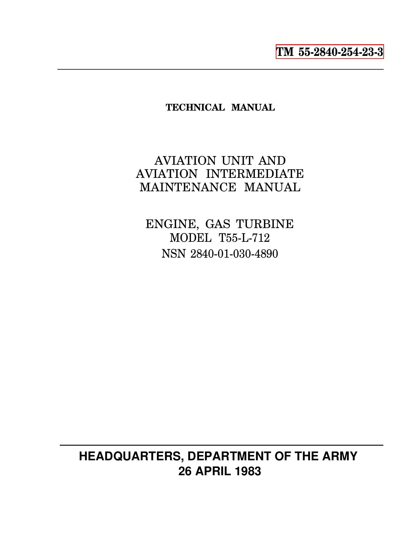
T55-L-712 Gas Turbine Engine Aviation Unit and Intermediate Maintenance Manual TM 55-2840-254-23-3
Original price was: $39.95.$24.95Current price is: $24.95.
Comprehensive Department of the Army technical manual TM 55-2840-254-23-3 providing Aviation Unit (AVUM) and Aviation Intermediate Maintenance (AVIM) instructions for the T55-L-712 gas turbine engine. Covers complete maintenance, disassembly, cleaning, non-destructive inspection, repair, assembly, and installation procedures for the combustion section, turbine section, and accessory gearbox.
Description
T55-L-712 Gas Turbine Engine Aviation Unit and Intermediate Maintenance Manual TM 55-2840-254-23-3
The T55-L-712 Gas Turbine Engine Aviation Unit and Intermediate Maintenance Manual TM 55-2840-254-23-3 is the official Department of the Army technical publication establishing authorized Aviation Unit Maintenance (AVUM) and Aviation Intermediate Maintenance (AVIM) procedures for the T55-L-712 turboshaft powerplant (NSN 2840-01-030-4890). Operating as primary heavy-lift propulsion for the Boeing CH-47 and MH-47 Chinook helicopter series, the high-performance T55 gas turbine requires uncompromising technical precision during scheduled servicing, modular maintenance, and depot-level intermediate overhaul. This third volume of the master technical manual suite provides direct, task-by-task workshop instructions for three foundational engine assemblies: the complete combustion section, the multi-stage gas producer and power turbine module, and the forward accessory drive gearbox.
File Details
- Manual Type: Aviation Unit and Aviation Intermediate Maintenance Manual (AVUM and AVIM)
- Equipment Identification: Engine, Gas Turbine, Model T55-L-712
- National Stock Number (NSN): 2840-01-030-4890
- Document Number: TM 55-2840-254-23-3 (Volume 3 of 4)
- Publishing Authority: Headquarters, Department of the Army
- Original Issue Date: 26 April 1983
- Revision Status: Active, incorporating Changes 1 through 7 (C1 through C7, up to 1 August 2005)
- Total Page Count: 946 pages
- Applicable Airframe: CH-47 / MH-47 Chinook Helicopter Series
- Authorized Personnel Skill Levels: MOS 68B10 Aircraft Powerplant Repairer and MOS 68B30 Aircraft Powerplant Inspector
- Language: English
- File Format: Portable Document Format (.pdf)
Combustion Section Maintenance Procedures
Chapter 3 of this TM 55-2840-254-23-3 maintenance manual details intermediate and unit maintenance covering the entire combustion architecture. Technicians are provided with complete procedural setups, required tool lists, expendable materials, and safety directives for servicing external components and internal combustor assemblies. Step-by-step instructions govern the removal, cleaning with dry cleaning solvent (E17), non-destructive testing, and installation of the lower 6-o clock fuel drain valves, including mandatory bolt torque checks of 40 to 45 inch-pounds with lockwire (E29) security. AVIM operations guide specialists through splitting the combustion section and power turbine from the compressor air diffuser assembly, utilizing the power turbine fixture (T54), hoist lifting gear, matchmarking alignment, and controlled mechanical separation using jacking bolts across the mounting flange. Detailed teardown procedures cover the extraction of the combustion chamber housing, fuel spray manifolds, starting fuel solenoid lines, start fuel nozzles, ignition leads, and the four-segment combustion chamber vane assembly. Step-by-step restoration tasks outline solvent washing with methyl ethyl ketone (E36), crack and burn inspection criteria for the combustion chamber liner, spotweld integrity checks, and precise mechanical straightening of distorted vane segments using custom hardwood blocks and soft-faced mallets. Full repair guidance for replacing swirler assemblies using clinching tool T41 and swirler installation fixtures guarantees that fuel-air mixing geometry conforms to original factory tolerances.
Turbine Section Overhaul, Balancing, and Clearances
Turbine section maintenance detailed in Chapter 4 encompasses the gas producer turbine stages, the free power turbine rotor assemblies, interstage stationary nozzles, and bearing structures. Technicians are guided through removal, inspection, overhaul, and testing of the dual-lead thermocouple jumper systems, left- and right-hand bus bar harnesses, and circumferential fireshield assemblies. Extensive electrical test matrices define multimeter resistance criteria (1,000 ohms minimum insulation resistance, zero ohms continuity on conductors, and 0.7 to 2.8 ohms specific harness lead loops). Specialized mechanical procedures cover the extraction and field service of the first and second turbine disc assemblies, third turbine nozzle and support, fourth stage power turbine nozzle, third stage power turbine rotor, and fourth stage power turbine rotor. Removal and reinstallation of the heavy power turbine rotor utilizing torque multiplier T63, torque fixture T48, and hydraulic wheel puller T58 require high-load torquing of the shaft retaining nut to 475 foot-pounds, followed by locking cup engagement. Thermal fitting routines specify controlled heating with induction heater T50 and control unit T55 for a maximum of 10 minutes (or 9 minutes on bearing packages), with optional dry ice shaft chilling. Critical axial clearance determinations between the second turbine disc assembly and third turbine nozzle must meet a 0.045 inch minimum limit, calibrated via selective shim packages (Part Nos. 2-141-199-01, 2-141-199-02, and 2-141-199-03). Third turbine rotor axial clearance is established at 0.101 inch minimum, while power turbine blade tip clearances across eight circumferential clock positions require a 0.020 inch minimum limit, and rotor face runout is held within an ultra-precise 0.003 inch total indicator reading.
Accessory Gearbox and Internal Drive Assemblies
Chapter 5 delivers complete workshop coverage for the T55-L-712 accessory gear section. Maintenance personnel are provided with exact sequences for uncoupling, inspecting, repairing, and reinstalling the accessory gearbox casing, internal spur and bevel drive gearing, starter drive adapter housings, overspeed switch drives, and auxiliary pad covers. Procedures ensure proper gear backlash inspection, oil seal replacement, drive spline wear assessments, and secure torque retention with double-twist safety wiring across all mounting flanges.
Chapters Covered
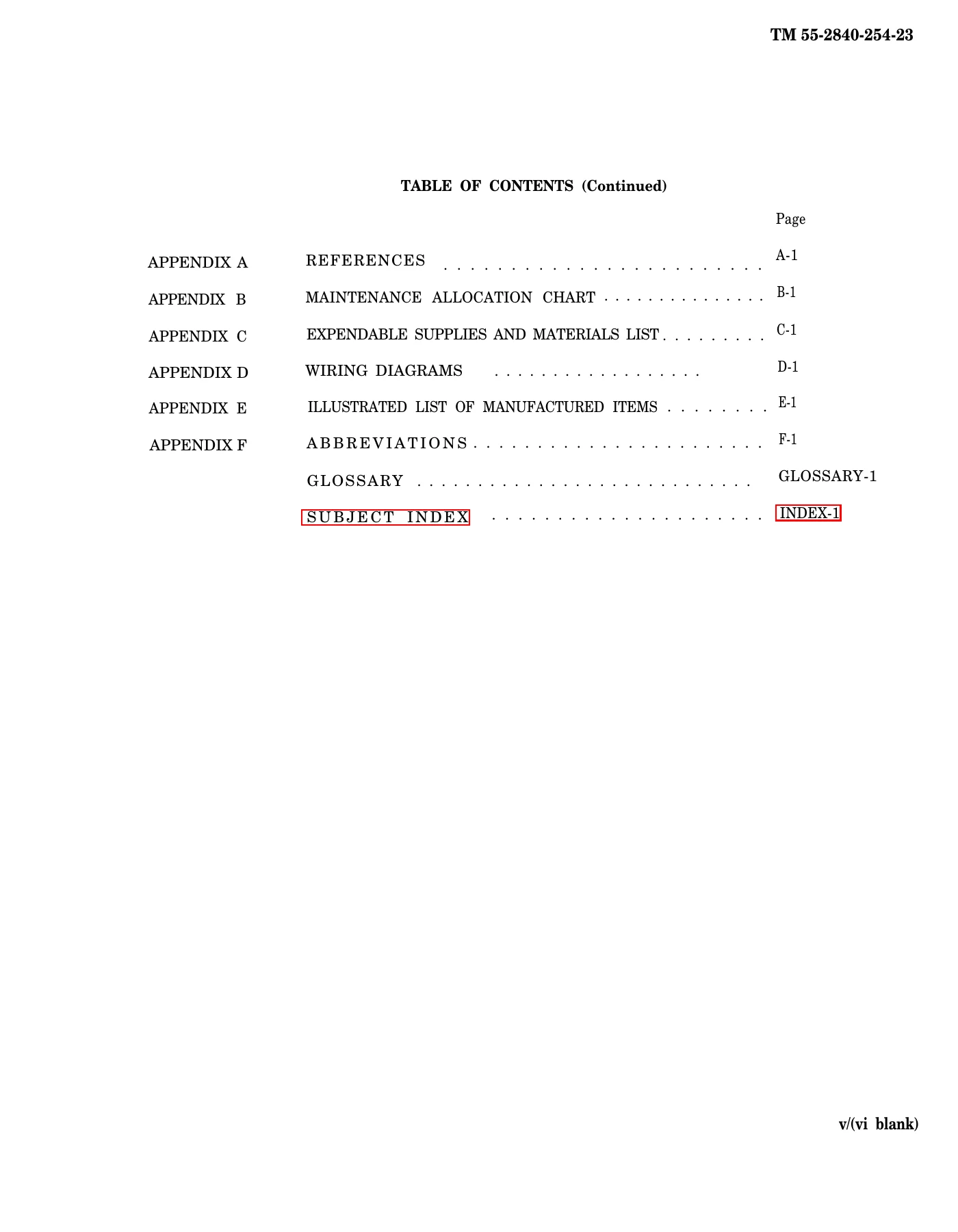
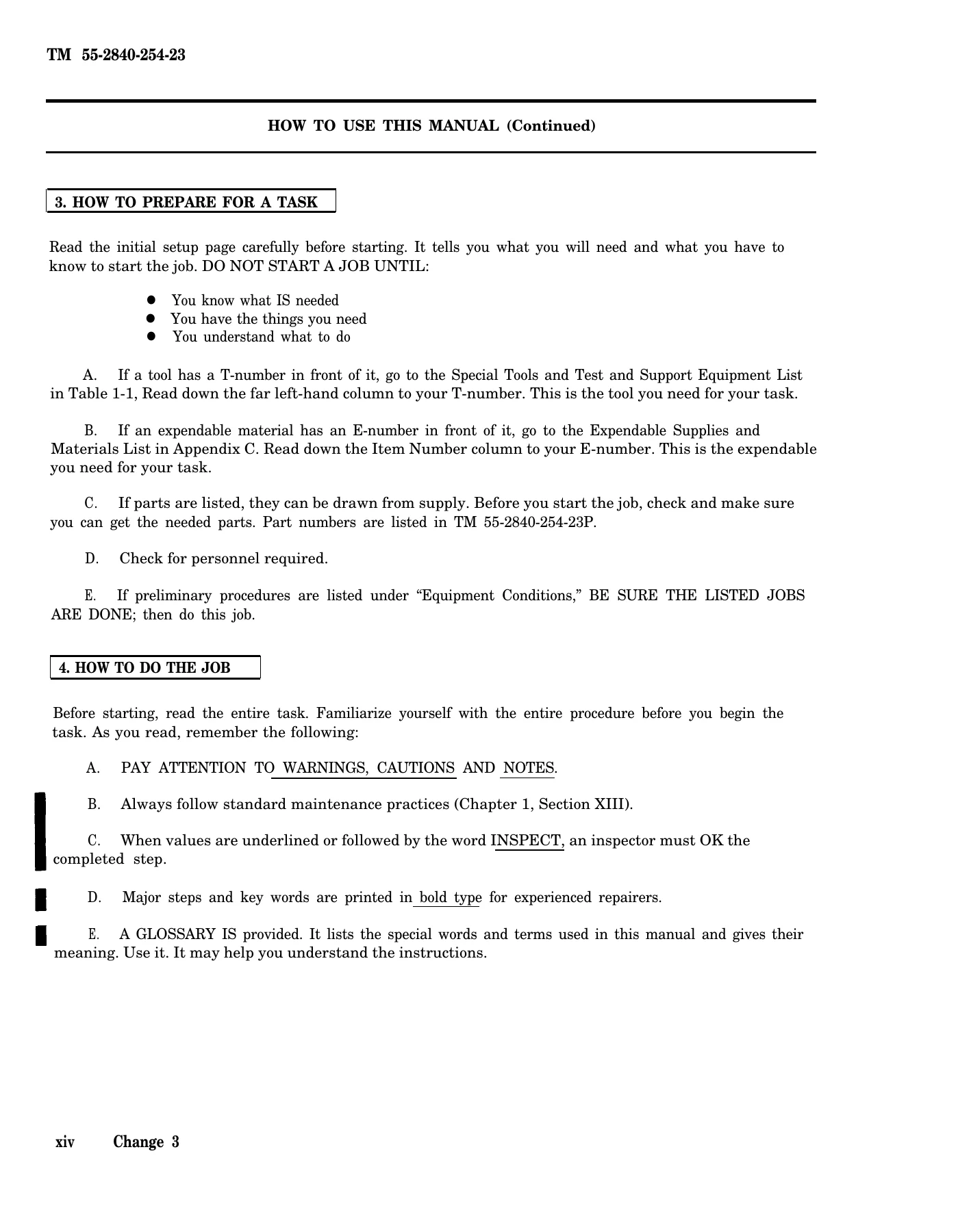
- Front Matter: General Safety Warnings, First Aid Data, List of Effective Pages (LEP), Master Table of Contents, and How To Use This Manual Guide
- Chapter 3: Combustion Section – Maintenance Instructions
- Section I: Fuel Drain Valve – Maintenance Procedures (Tasks 3-1 through 3-4)
- Section II: Combustion Section and Power Turbine – Maintenance Procedures (Tasks 3-5 through 3-8)
- Section III: Combustion Section – Maintenance Procedures (Tasks 3-9 through 3-12)
- Section IV: Combustion Chamber Vane Assembly – Maintenance Procedures (Tasks 3-13 through 3-15)
- Section V: Combustion Chamber Liner – Maintenance Procedures (Tasks 3-16 through 3-18)
- Section VI: Combustion Chamber Housing – Maintenance Procedures (Tasks 3-19 through 3-21)
IMAGES PREVIEW


- Chapter 4: Turbine Section – Maintenance Instructions
- Section I: Thermocouple Jumper Lead – Maintenance Procedures (Tasks 4-1 through 4-6)
- Section II: Left- and Right-Hand Bus Bar Assemblies – Maintenance Procedures (Tasks 4-7 through 4-11)
- Section III: Fireshield Assembly – Maintenance Procedures (Tasks 4-12 through 4-15)
- Section IV: Fireshield Section – Maintenance Procedures (Tasks 4-16 through 4-19)
- Section V: Thermocouple Harness Assemblies – Maintenance Procedures (Tasks 4-20 through 4-25)
- Section VI: Third Turbine Nozzle and Support – Maintenance Procedures (Tasks 4-26 through 4-32)
- Section VII: Fourth Stage Power Turbine Rotor – Maintenance Procedures (Tasks 4-33 through 4-36)
- Section VIII: No. 4 and 5 Bearing Package – Maintenance Procedures (Tasks 4-37 through 4-44)
- Section IX: Fourth Stage Power Turbine Nozzle – Maintenance Procedures (Tasks 4-45 through 4-49)
- Section X: Third Stage Power Turbine Rotor – Maintenance Procedures (Tasks 4-50 through 4-52)
- Section XI: Second Turbine Disc Assembly – Maintenance Procedures (Tasks 4-53 through 4-56)
- Section XII: Second Turbine Nozzle, Spacer, and Case – Maintenance Procedures (Tasks 4-57 through 4-61)
- Section XIII: First Turbine Disc Assembly – Maintenance Procedures (Tasks 4-62 through 4-66)
- Section XIV: First Turbine Nozzle – Maintenance Procedures (Tasks 4-67 through 4-71)
- Section XV: Field Replacement First and Second Turbine Disc Assembly (Task 4-72)
- Section XVI: Diffuser Curl – Maintenance Procedures (Tasks 4-73 through 4-77)
- Section XVII: Exit Vane Assembly – Maintenance Procedures (Tasks 4-78 through 4-82)
- Chapter 5: Accessory Gear Section – Maintenance Instructions
- Section I: Chapter Overview (Task 5-1)
- Section II: Accessory Gearbox Assembly Maintenance Procedures (Tasks 5-2 through 5-7)
- Section III: Accessory Gear Assembly Maintenance Procedures (Tasks 5-8 through 5-14)
- Section IV: Starter Drive Assembly – Maintenance Procedures (Tasks 5-15 through 5-19)
- Section V: Overspeed Drive and Outlet Cover Assembly – Maintenance Procedures (Tasks 5-20 through 5-24)
- Back Matter: Comprehensive Alphabetical Subject Index (Index-1 through Index-32)
As an integrated technical document, this maintenance manual provides aircraft powerplant mechanics, military aviation contractors, and turbine overhaul facilities with exhaustive, field-proven maintenance procedures. By outlining initial setup requirements, specialized T-numbered support equipment, expendable consumable codes, step-by-step teardown workflows, and mandatory technical inspection limits, this volume eliminates guesswork and ensures that every engine returned to service adheres to strict military airworthiness requirements.
Professional Capability and Instant PDF Delivery
Working on advanced gas turbine powerplants demands absolute adherence to certified technical instructions, exact torque limits, and manufacturer-mandated service tolerances. The T55-L-712 Gas Turbine Engine Aviation Unit and Intermediate Maintenance Manual TM 55-2840-254-23-3 equips aviation technicians with the authoritative data needed to conduct flawless hot-section inspections, turbine rotor balancing, bearing seal overhauls, and complete combustor rebuilds. Procuring this verified technical manual provides immediate digital access without shipping delays or backorders. The complete PDF file is delivered instantly after checkout, ready for viewing on desktop computers, workshop diagnostic laptops, or mobile tablets in the hangar. The document is fully printable, enabling mechanics to print out high-resolution assembly diagrams, wiring schematics, and task setup sheets directly at the workbench for safe, compliant, and efficient flight-line operations.

Reviews
There are no reviews yet.