
Thrush S2RHG-T65 Turbo Thrush Single & Dual Cockpit Aircraft Maintenance Manual 2005
Original price was: $39.95.$23.95Current price is: $23.95.
A 272-page Thrush Aircraft, Inc. maintenance manual for the S2RHG-T65 Turbo Thrush in single- and dual-cockpit configurations. Covers servicing, inspections, PT6 powerplant and propeller installation, fuel, landing gear, flight controls, instruments, dispersal systems, electrical diagrams and airworthiness limitations.
Description
Thrush S2RHG-T65 Turbo Thrush Single & Dual Cockpit Aircraft Maintenance Manual 2005
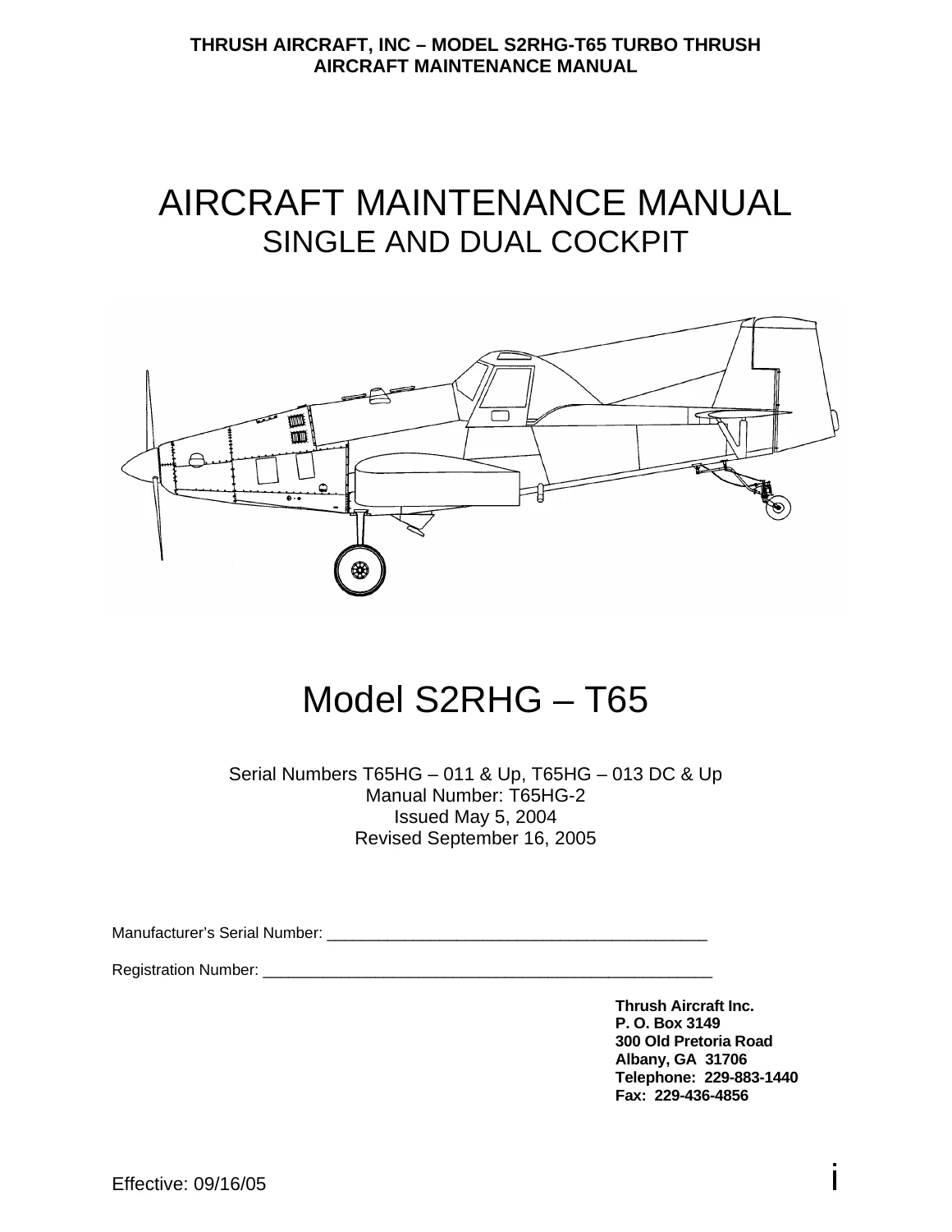
This aircraft maintenance manual is a detailed technical reference for the Thrush S2RHG-T65 Turbo Thrush in single- and dual-cockpit configurations. Manual T65HG-2 was issued May 5, 2004 and revised September 16, 2005, with coverage identified for serial numbers T65HG – 011 & Up and T65HG – 013 DC & Up. Across 272 pages, the manual brings together aircraft-specific servicing, inspection, system description, removal and installation work, rigging, troubleshooting, limits, drawings, and wiring information for technicians maintaining the S2RHG-T65.
File Details
- Manual type: Aircraft Maintenance Manual
- Brand: Thrush Aircraft, Inc.
- Model: S2RHG-T65 Turbo Thrush, single and dual cockpit
- Serial coverage: T65HG – 011 & Up; T65HG – 013 DC & Up
- Manual number: T65HG-2
- Issued: May 5, 2004
- Revised: September 16, 2005
- Language: English
- Pages: 272
- File format: PDF
Maintenance, Inspection and Service Depth
The Thrush S2RHG-T65 Turbo Thrush Single & Dual Cockpit Aircraft Maintenance Manual 2005 is built around the practical work needed to keep the aircraft serviceable. The servicing and inspection section covers ground handling, towing, taxiing, parking, mooring, jacking and leveling, cold-weather practices, ground emergency procedures, engine starting and operational checks, routine servicing, defueling, brake bleeding, corrosion control, windshield care and battery maintenance. Its inspection material extends through propeller, engine externals, engine oil and fuel systems, ignition, pneumatic equipment, airframe fuel, landing gear, tail gear, fuselage, hopper, wings, controls, empennage, cockpit and electrical items, with inspection intervals shown for daily, 50-hour, 100-hour and 400-hour work where applicable.
Lubrication receives its own illustrated chart sequence, and the manual includes a general torque chart plus engine-oil servicing illustrations. The aircraft-specific inspection material is particularly useful for agricultural service because it repeatedly addresses cleaning, chemical exposure, corrosion prevention, hopper condition, wing and fuselage structure, fuel-system drains and control-system condition. This gives the technician a single reference for scheduled checks as well as the follow-on section to consult when an inspection reveals a problem that needs deeper system work.
Powerplant, Propeller and System Work
Powerplant coverage applies to installations using Pratt & Whitney Canada PT6A-45A, PT6A-45B, PT6A-45R, PT6A-60AG, PT6A-65AG, PT6A-65AR and PT6A-65B engines. The manual states that the dual-cockpit version is approved with the PT6A-60AG engine only at the time of this revision. The powerplant and propeller section goes beyond a basic description: it covers engine buildup, engine removal and installation, propeller operation, beta feedback, the constant speed unit, overspeed governor, engine power and propeller controls, feathering, propeller removal and installation, governor work, control-linkage rigging, idle adjustments and operational checks. Engine installation data, propeller settings and illustrated component layouts support accurate setup after maintenance.
The fuel-system chapter covers the 230 U.S. gallon aircraft fuel supply, quantity indicating system, transmitters, calibration, electric and engine-driven fuel pumps, filter servicing, fuel-line maintenance, wet-wing sealing compounds, leak sealing, resealing after skin removal and a troubleshooting chart. Landing-gear coverage includes the main gear, tail gear, wheel and brake assemblies, brake lining wear, organic and metallic lining procedures, conditioning, master cylinders and brake bleeding. Flight-control material addresses the control stick, ailerons, flaps, rudder, elevators, trim systems, empennage, wing removal and installation, rigging and troubleshooting, supported by detailed drawings and balance information.
Chapters Covered
- Section 1 – General Information
- General description and principal dimensions
- Aircraft structure: fuselage, wing, empennage and cockpit
- Aircraft systems, component manuals, three-view and aircraft stations
- Section 2 – Servicing & Inspection
- Ground handling, cold-weather operation and emergency procedures
- Ground engine operation and routine system/component servicing
- Inspection checklist and scheduled inspection charts
- Corrosion control, windshield, hopper, fuel tank and battery maintenance
- Lubrication, torque and engine-oil servicing figures
- Section 3 – Hydraulics
- Hydraulic brake-system description and operation
- Section 4 – Powerplant and Propeller
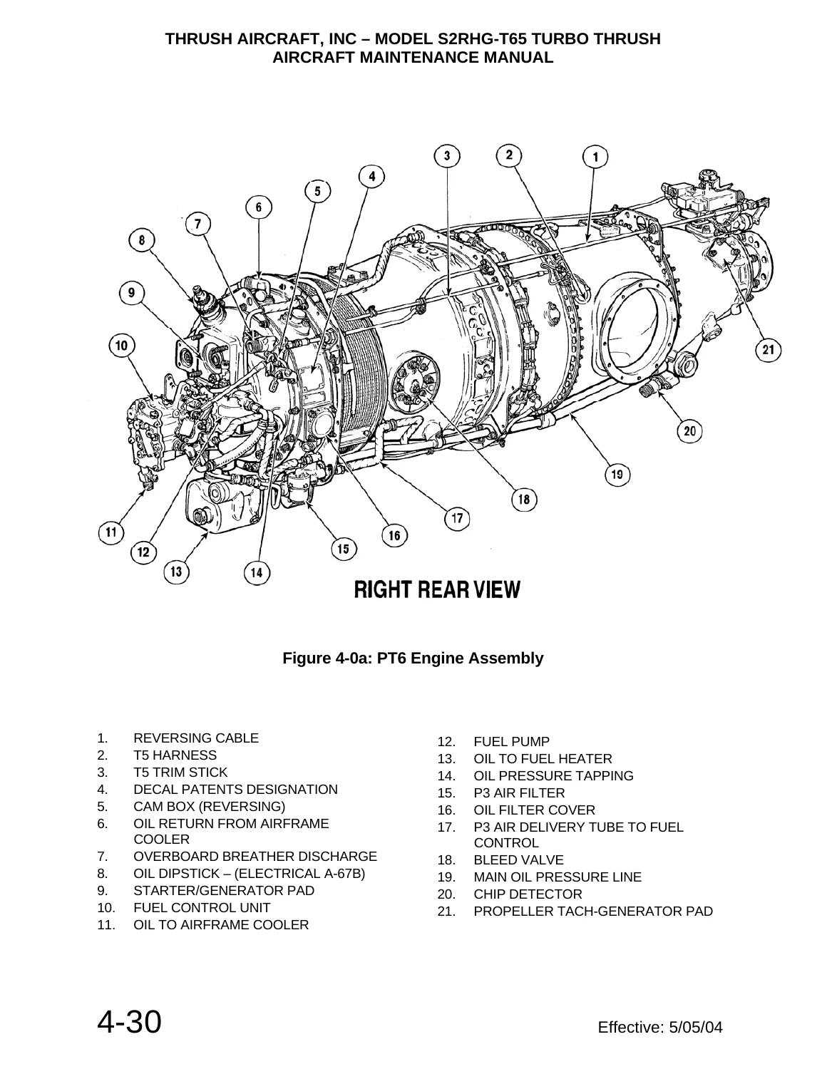
- PT6 powerplant description, air cleaning, engine buildup, removal and installation
- Propeller, beta feedback mechanism, CSU and overspeed governor
- Propeller maintenance, removal, installation and governor procedures
- Airframe/engine control-linkage rigging and propeller rigging
- Ground idle, flight idle, governor, feathering, reverse and torque-setting checks
- Engine installation data and component diagrams
- Section 5 – Fuel System
- Fuel quantity indication, transmitter removal, installation and calibration
- Auxiliary and engine-driven fuel pumps and fuel-filter servicing
- Fuel-line maintenance, sealing compounds and wet-wing leak repair
- Fuel-system troubleshooting and hopper ferry-fuel system
- Section 6 – Landing Gear, Wheels & Brakes
- Main and tail landing-gear removal, inspection, repair and installation
- Tail-wheel disassembly, inspection, reassembly and rigging
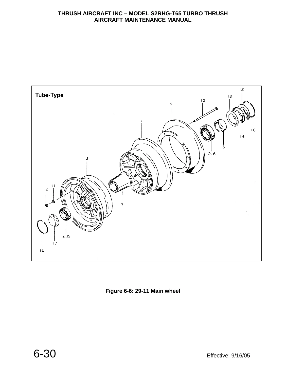
- Main-wheel removal, inspection and reassembly
- Organic and metallic brake lining service and conditioning
- Brake overhaul, master cylinders, bleeding and troubleshooting
- Section 7 – Flight Controls
- Control stick, ailerons, flaps, rudder and elevators
- Control-surface removal, installation and rigging
- Empennage and wing removal and installation
- Control-system troubleshooting and static balance limits
- Section 8 – Instruments
- Pitot-static system, altimeter, airspeed indicator and magnetic compass
- Powerplant and miscellaneous instruments
- Instrument troubleshooting and PT6-series instrument markings
- Section 9 – Dispersal Systems
- Hopper care, repair, gate box and adapter box work
- Dispersal equipment, agitator, spreader and spray-boom illustrations
- Section 10 – Electrical System
- Power distribution, battery/external power, generator and voltage regulation
- Starter-generator maintenance and electrical troubleshooting
- System schematics, wire routing, quick-disconnect layouts and equipment circuits
- Section 11 – Airworthiness Limitations
- Structural limitations and structural inspection limitations
Taken as a whole, the manual connects inspection findings to aircraft-system maintenance rather than treating each component in isolation. It provides the dimensions, limits, rigging information, service procedures, fault-isolation charts and illustrations needed to work across the airframe, propulsion installation, fuel system, landing gear, controls, instruments, agricultural dispersal equipment and electrical system.
Aircraft-Specific Reference and Supplier Manual Boundaries
This S2RHG-T65 aircraft maintenance manual is focused on Thrush-specific installations and procedures. It directs certain engine-internal, propeller and supplier-component work to the applicable Pratt & Whitney or component manuals, and it states that detailed descriptions of standard workshop procedures, general safety principles and standard service operations are not reproduced. That boundary is useful when planning a job: this manual supplies the aircraft installation, inspection, rigging, removal/installation, troubleshooting and system information while identifying where a referenced component manual is required for deeper component-specific work.
Maintain and Repair Your Turbo Thrush with the Right Technical Reference
Use the Thrush S2RHG-T65 Turbo Thrush Single & Dual Cockpit Aircraft Maintenance Manual 2005 when servicing the aircraft, tracing fuel or electrical faults, inspecting structural and control-system items, removing or installing major assemblies, rigging flight or engine controls, checking propeller operation, maintaining landing gear and brakes, or working with the hopper and dispersal installation. Correct procedures, settings, inspection criteria and system diagrams matter when maintenance decisions directly affect aircraft serviceability and safety. Your purchase is delivered as an instant PDF with no shipping wait; open it on a compatible phone, tablet or computer and print the pages you need for workshop use.
Reviews
There are no reviews yet.