
Volvo EW160C Hydraulic & Digging Handling Grading Systems Service Manual – PDF Download
Original price was: $59.95.$39.95Current price is: $39.95.
Complete 558-page Volvo EW160C service manual covering hydraulic system, digging handling and grading systems. Instant PDF download for workshop and field repairs.
Description
File Details
- Manual Type: Service Information / Workshop Manual
- Brand: Volvo Construction Equipment
- Model: EW160C (with selected coverage for EW140C, EW180C, EW210C, EW230C)
- Language: English
- Page Count: 558 pages
- File Format: PDF
- Document Date: 2014/4/24
- Profile: EXC, EW160C [GB]
Chapters Covered
- 900 – Hydraulic Oil, Storage, Cleanliness & Vacuum Pump Procedures
- 910 – Hydraulic System Description, Load Holding Valves & Complete Hydraulic Diagrams
- 911 – Cooling System, Hydraulic Oil Tank & Thermostatic Function
- 912 – Main Control Valve Block, Back-Up Valves, Pressure Relief & Rupture Valves
- 913 – Working Pump Description, Removal & Shaft Seal Replacement
- 914 – Servo System, Pressure Accumulators, Servo Valve & Servo Pump
- 915 – Control Lever Removal & Installation
- 916 – Optional Hydraulic Equipment (X1, X3, Boom Float, Cruise Control, Reversible Fan, Pattern Change, Grab Bucket, Offset Boom, Tiltrotator)
- 924 – Hydraulic Quickfit Description, Cylinder Service & Function Checks
- 970 – Hydraulic Cylinder Description, Troubleshooting, Bearings & Bushing Replacement
- 972 – Stabilisers and Stabiliser Blade Description & Cylinder Service
- 974 – Boom, 2-Piece Boom, Boom Cylinder & Tilt Cylinder Service
- 975 – Dipper Arm, Dipper Arm Cylinder & Bucket Cylinder Service
- 993 – Automatic Lubrication System Description, Control Unit & Troubleshooting
- 996 – Hydraulic Elevating Cab Description & Cylinder Replacement
900 – Hydraulic Oil & General Service Information
This opening section covers the hydraulic oil itself, including additive composition and low-temperature characteristics. It lays out storage and transport rules for hydraulic components, emphasises cleanliness when handling hydraulic components, and provides complete procedures for connecting and disconnecting a vacuum pump to the hydraulic oil tank. A keypad-based procedure for reading hydraulic oil temperature through the I-ECU is also included.
910 – Hydraulic System Description & Diagrams
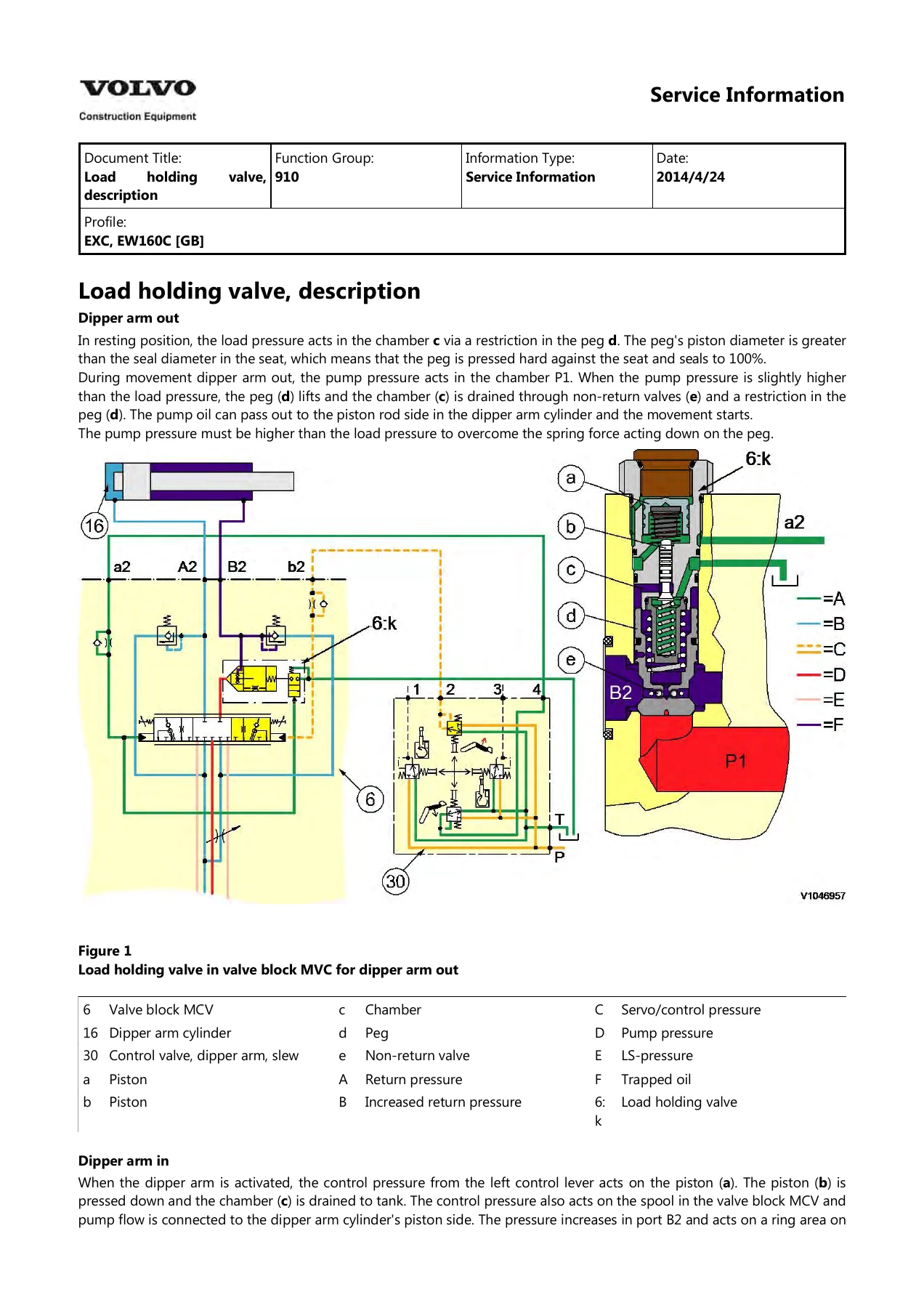
The complete working and servo hydraulic system is described here, including the load-sensing variable-flow principle and the function of valve spools and compensators inside the main control valve block. A load-holding valve description for dipper arm out and dipper arm in is supported by detailed colour cutaway diagrams. This section also contains an extensive set of complete hydraulic diagrams covering the main circuit, boom float valve, dozer blade and outrigger, X1 with pressure control, X1 with flow control, X3, cruise control, quick fit, grab piping, offset boom, reversible cooling fan, and control pattern selector valve. Flushing recommendations after major component failure are also provided.
911 – Cooling System & Hydraulic Oil Tank
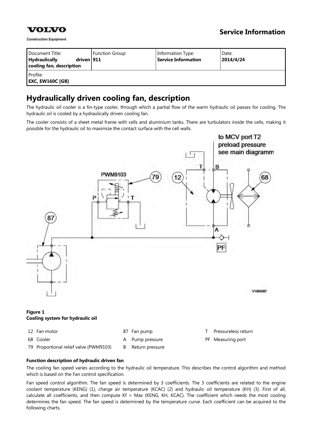
Hydraulically driven cooling fan operation is explained, including the fan speed control algorithm based on engine coolant, charge air, and hydraulic oil temperature. Procedures are given for checking and adjusting the cooling fan control valve, checking fan speed with and without VCADS Pro, and removing and installing the cooling fan pump, fan motor, and hydraulic oil cooler. The hydraulic oil tank section covers its construction, thermostatic function for rapid warm-up, pressure release, removal, and installation. A chart-based thermostatic function description shows how the proportional valve PWM9104 controls oil flow to the cooler.
912 – Main Control Valve Block & Pressure Control
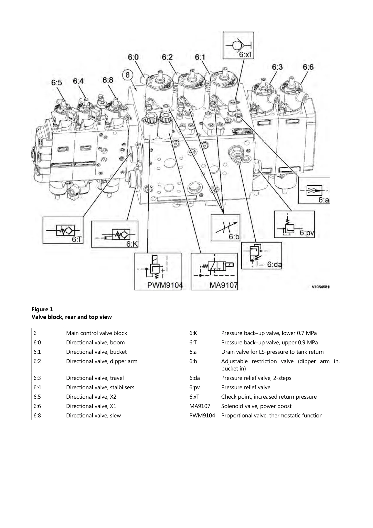
The main control valve block (MCV) is described with its directional valves for boom, dipper arm, bucket, travel, stabilisers, slew, adjustable boom X2, and optional equipment X1. Back-up valve functions are detailed, including anti-cavitation, hydraulic oil cooler protection, regeneration, and thermostatic function. Checking and adjusting procedures are provided for back-up valves, working pressure (Δp), pump pressure, power boost pressure, and secondary pressure limiting valves. Shock and anti-cavitation valve operation is explained with cutaway illustrations. Rupture valve replacement procedures cover boom cylinder, dipper arm cylinder, and 2-piece boom tilt cylinder applications. Dipper arm in speed checking and adjustment is also included, along with LS-pressure relief valve and safety relief valve replacement.
913 – Working Pump
The working pump section describes the rotary plate axial piston design with variable displacement, controlled by load-sensing LS and electric signals from the V-ECU. The pump regulator is explained with its adjusting screws for maximum and minimum displacement, Δp, and control pressure. A complete hydraulic diagram for the working pump is included. Procedures cover pump removal, installation, and shaft seal replacement with special tools.
914 – Servo System
The servo hydraulic system is described with its servo gear pump, relief valve block, accumulator, and control lockout lever safety function. Pressure accumulator construction and function are explained, including servo circuit and brake circuit accumulators. Servo valve removal and installation, servo pump removal and installation, and servo pressure checking and adjusting procedures are provided. The control lockout lever function check is described with preconditions and expected outcomes. A servo pump troubleshooting table covers pressure, noise, heating, foaming, and shaft seal leakage problems.
915 – Control Levers
Left and right remote control valve removal and installation procedures are provided, with port and line position identification for both sides. Console cover removal, wire harness disconnection, and control valve bolted joint removal are described in sequence. Installation reverses the procedure with hose connection details for slew, dipper arm, bucket, and boom functions.
916 – Optional Hydraulic Equipment
This extensive section covers X1 flow-controlled and pressure-controlled systems with descriptions of the flow control valve, pressure control valve, solenoid valves, and proportional valves. X1 calibration procedures with VCADS Pro are provided for both flow and pressure control. X3 equipment is described with on/off and proportional control options, pressure and flow adjustment procedures, and a function check. Boom float position, cruise control, reversible cooling fan, control pattern change valve, grab bucket, and offset boom are each described with hydraulic diagrams. The tiltrotator control system section covers function description, quick fit control, display descriptions in service mode, auto-tuning, settings, calibration, and troubleshooting.
924 – Hydraulic Quickfit
The hydraulic quickfit description explains the locking principle with spring force and constant servo pressure on the piston side. Quickfit open and closed sequences are shown with hydraulic diagrams. Cylinder removal and installation procedures are provided for both S1 and S6 quickfit models. The quickfit removal, installation, and function check procedures complete this section.
970 – Hydraulic Cylinders & Digging Equipment Bearings
General cylinder construction and cushioning operation are described with cutaway diagrams. A comprehensive troubleshooting table covers piston rod scoring, oil leaks, cylinder tube damage, loose pistons, internal leakage, abnormal noise, and heavy impact. Boom lifting cylinder, dipper arm cylinder, and bucket cylinder descriptions include component breakdowns and tightening torques. Digging equipment bearing radial clearance measurement and shimming procedures are provided with connection point diagrams and maximum clearance values. Bushing replacement is covered with part numbers for puller plates by model and position. Hydraulic cylinder creeping measurement procedures and specifications are also included.
972 – Stabilisers
Stabiliser and stabiliser blade operation is described with electric diagrams for front blade/rear legs and front/rear legs configurations. Hydraulic diagrams show blade operation down and up, rear legs operation down and up, and combined front and rear leg operation. Stabiliser cylinder removal and installation procedures are provided with sling positioning and pin driving instructions.
974 – Boom & Boom Cylinders
Boom removal and installation procedures cover dipper arm removal, boom cylinder depressurisation, lubrication hose disconnection, pin removal with impact puller, and sling positioning. 2-piece boom removal and installation are described with tilt cylinder support, hose disconnection, and pin removal. Boom cylinder removal and installation procedures include line rupture valve transfer, piston rod bleeding, shimming, and pin lock fitting. Tilt cylinder 2-piece boom removal and installation are also covered, along with bushing replacement procedures.
975 – Dipper Arm & Bucket Cylinder
Dipper arm removal and installation procedures are provided with sling positioning, pin removal, and hose connection details. Dipper arm cylinder removal and installation cover pin removal with impact puller, hose disconnection, bleeding, and shimming. Bucket cylinder removal and installation procedures are described with quickfit hook positioning, hose disconnection, piston rod bleeding, and pin lock fitting. Bushing replacement procedures for dipper arm-boom, dipper arm-bucket, dipper arm-lever, and bucket cylinder bushings are listed with cross-references to the bushing replacement section.
993 – Automatic Lubrication System
The automatic lubrication system is described with its lubrication unit, master feeder, cycle switch, secondary feeders, and pipe network. Pump control unit operation is explained with display codes for pause, contact, fault, and block mode. Software functions including block mode, code displays, display mode changing, lubrication cycle changing, and system monitoring type changing are detailed with step-by-step button sequences. Troubleshooting covers stirring arm malfunction, pump without function, excessive or insufficient grease, and fault displays FLL, FCS, and bLo. Bleeding air procedures and scheduled maintenance overview complete this section.
996 – Hydraulic Elevating Cab
The hydraulic elevating cab description covers the cab supporting frame, parallel moving mechanism, hydraulic lifting cylinders, and pressure accumulators. Safety rules for working under the raised cab and emergency cab lowering procedures are provided. The wiring diagram identifies solenoid valves, position sensors, switches, and buzzer. Cab elevating cylinder replacement is described step by step with cab supporting, pin removal using E-tool, shimming, and bleeding procedures.
Why This Volvo EW160C Service Manual Matters
This is not a generic hydraulic guide. Every procedure, specification, and diagram in this 558-page Volvo EW160C service manual was written for the wheeled excavator platform and its exact hydraulic and digging handling grading systems. The load-sensing working hydraulic circuit, the servo control circuit, the main control valve block with its back-up valves and pressure relief valves, the cooling fan control algorithm, the optional X1 and X3 circuits, the tiltrotator control system, the quickfit hydraulics, and the complete digging equipment cylinder and bushing service procedures are all documented with the level of detail a working technician needs.
Whether you are diagnosing a creeping boom cylinder, adjusting back-up valve pressures, replacing a line rupture valve, calibrating X1 pressure control with VCADS Pro, removing a 2-piece boom, shimming digging equipment bearings, or troubleshooting the automatic lubrication system, the correct procedure and the correct specification are in this manual. The hydraulic diagrams alone — covering the complete circuit, boom float, dozer blade and outrigger, X1 pressure and flow control, X3, cruise control, quick fit, grab piping, offset boom, reversible cooling fan, and control pattern selector valve — are worth the purchase for any workshop that services Volvo wheeled excavators.
IMAGES PREVIEW
Delivered as an instant PDF download, this manual is ready to use on any device. No shipping, no waiting. Print the pages you need for the workshop, or search the digital file on a laptop or tablet. Every procedure is written for the technician who needs to get the machine back to work correctly, with the right torque values, the right pressure settings, and the right sequence of operations.
Reviews
There are no reviews yet.