Description
Yamaha F200B FL200B F250H FL250H 4-Stroke Outboard Service Manual
This is the complete service manual for the Yamaha F200B, FL200B, F250H, and FL250H 4-stroke outboard motors. Published as the 2nd Edition in July 2021 under document number 6FJ-28197-50-11, it covers the 3352 cm3 (204.5 cu. in.) V6 DOHC 24-valve engine platform with electronic fuel injection. Whether you are servicing a single engine or a twin/triple installation, this manual provides the removal, disassembly, inspection, adjustment, assembly, and installation procedures needed to complete the job correctly.
File Details
- Manual type: Service Manual
- Brand: Yamaha
- Models covered: F200B, FL200B, F250H, FL250H
- Language: English
- Page count: 428
- File format: PDF
- Document number: 6FJ-28197-50-11
- Edition: 2nd Edition, July 2021
- Publisher: Yamaha Motor Co., Ltd.
Chapters Covered
The manual is organized into the following chapters and sections:
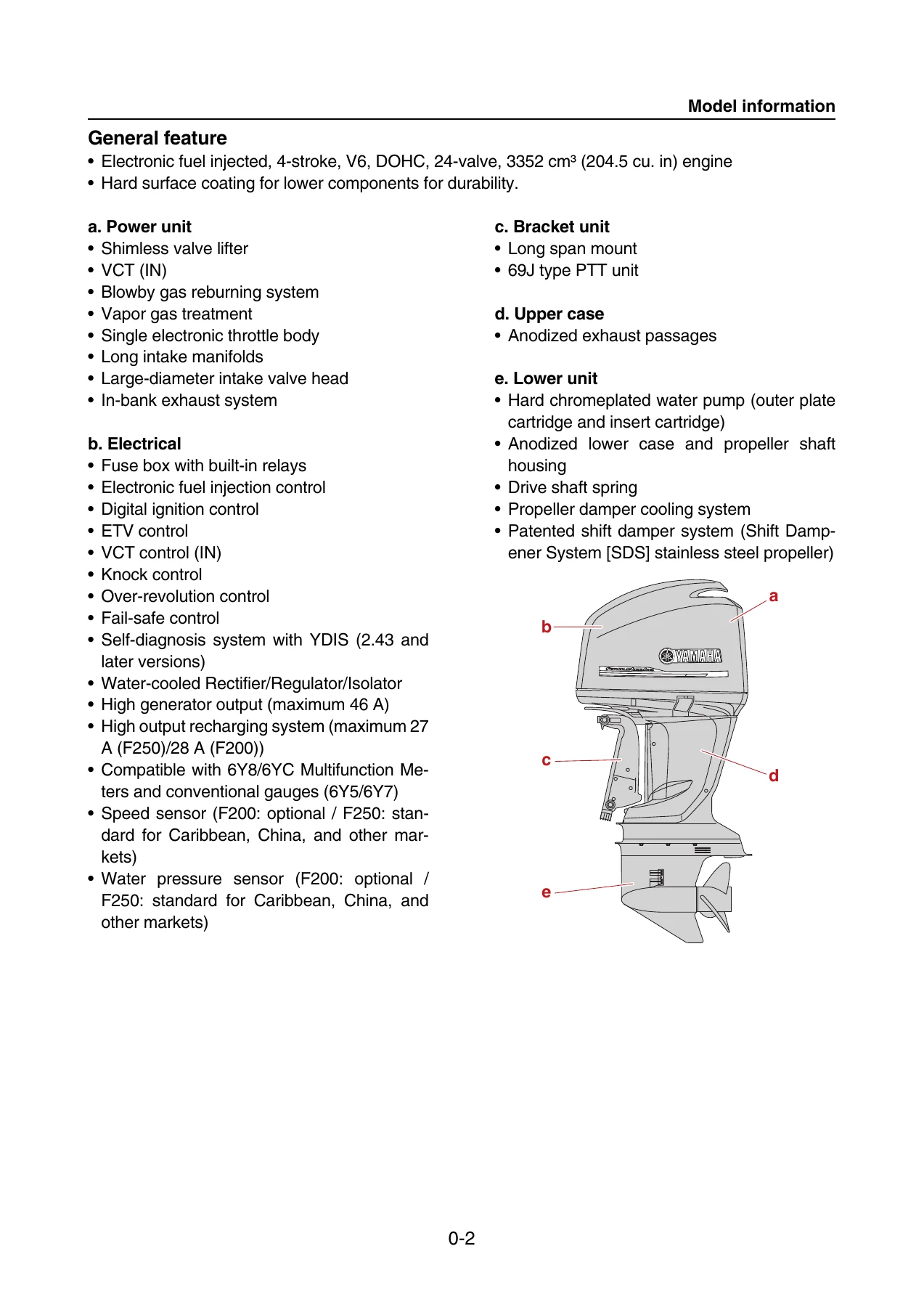
- General Information – Model information, important safety and service information, how to use this manual, specified tightening torque, symbols, special service tools
- Specification – General tightening torque specifications
- Technical Feature and Description – Electrical components, fail-safe, fuse box and relay, serviceability, lower unit (Shift Dampener System), fuel system, lubrication system, cooling system, intake and exhaust system, hose routing
- Rigging Information – Outboard motor mounting instructions, crate handling, uncrating, rigging grommet mounting, battery cable installation, shift cable, throttle cable, main wire harness, 6Y8/6YC multifunction meter harness, conventional gauge harness, optional equipment, battery installation, propeller selection
- Troubleshooting – YDIS, outboard motor troubleshooting, troubleshooting procedure, power unit using YDIS, trouble code and checking step, PTT unit, lower unit
- Electrical System – Wire harness routing (port, starboard, rear, top, bottom cowling), ECM circuit diagram, ECM coupler layout, checking electrical components, engine control unit, fuel control unit, ignition unit, starting unit, 6Y8/6YC multifunction meter sensor, PTT system
- Fuel System – Reducing fuel pressure, disconnecting quick connector, measuring fuel pressure, pressure regulator, fuel filter assembly, intake manifold, throttle body, ETV, low-pressure fuel pump, vapor separator, fuel injector
- Power Unit – Compression pressure, oil pressure, pulser coil air gap, valve clearance, power unit assembly, flywheel magneto, wire harness, fuse box, junction box, starter motor and APS, engine ECM, timing belt, cylinder head cover, camshaft, exhaust cover, cylinder head, cooling water cover, crankcase, cylinder block
- Lower Unit – Propeller, lower unit, extension (U-transom), water pump and shift rod, propeller shaft housing (regular and counter rotation), drive shaft and lower case (regular and counter rotation), shimming (regular and counter rotation)
- Bracket Unit – Shift rod and shift bracket, PTT switch and cowling lock lever, bottom cowling, upper case and mounts, upper case, oil pan and exhaust manifold, steering arm, clamp bracket and swivel bracket, PTT unit, PTT motor, PTT gear pump, PTT cylinder
- Maintenance – Outline, maintenance interval charts, predelivery check, general periodic maintenance
- Appendix – Specifications, wiring diagram, Rectifier/Regulator/Isolator continuity table, shim selection tables and charts
This Yamaha F200B FL200B F250H FL250H 4-Stroke Outboard Service Manual gives a technician the complete factory workflow for every major system on the engine. The power unit chapter alone takes you through valve clearance measurement and adjustment, timing belt removal and installation with alignment marks, camshaft removal and journal oil clearance measurement using Plastigauge, cylinder head disassembly with valve guide replacement and seat refacing procedures, crankshaft journal and pin bearing selection, piston ring end gap and side clearance checks, and full cylinder block assembly torque sequences. The lower unit chapters cover regular and counter rotation models separately, with shimming workflows that include pinion shim (T3), forward gear shim (T1/T2), reverse gear shim (T2/T1), and propeller shaft shim (T4) selection tables. The bracket unit chapter handles the PTT system in depth, with hydraulic pressure testing, gear pump disassembly and assembly, tilt ram and trim ram service, and electrical checks for the PTT motor, relay, and switches.
What This Manual Enables You To Do
With this service manual, you can perform a full range of jobs on the Yamaha F200B, FL200B, F250H, and FL250H outboards:
Complete PDF Bookmark Tree
Complete Bookmarks
The complete bookmarks in the βYamaha F200B FL200B F250H FL250H 4-Stroke Outboard Service Manual – 2021 2nd Edition PDFβ are as follows:
+Contentsp. 3
+General informationp. 4
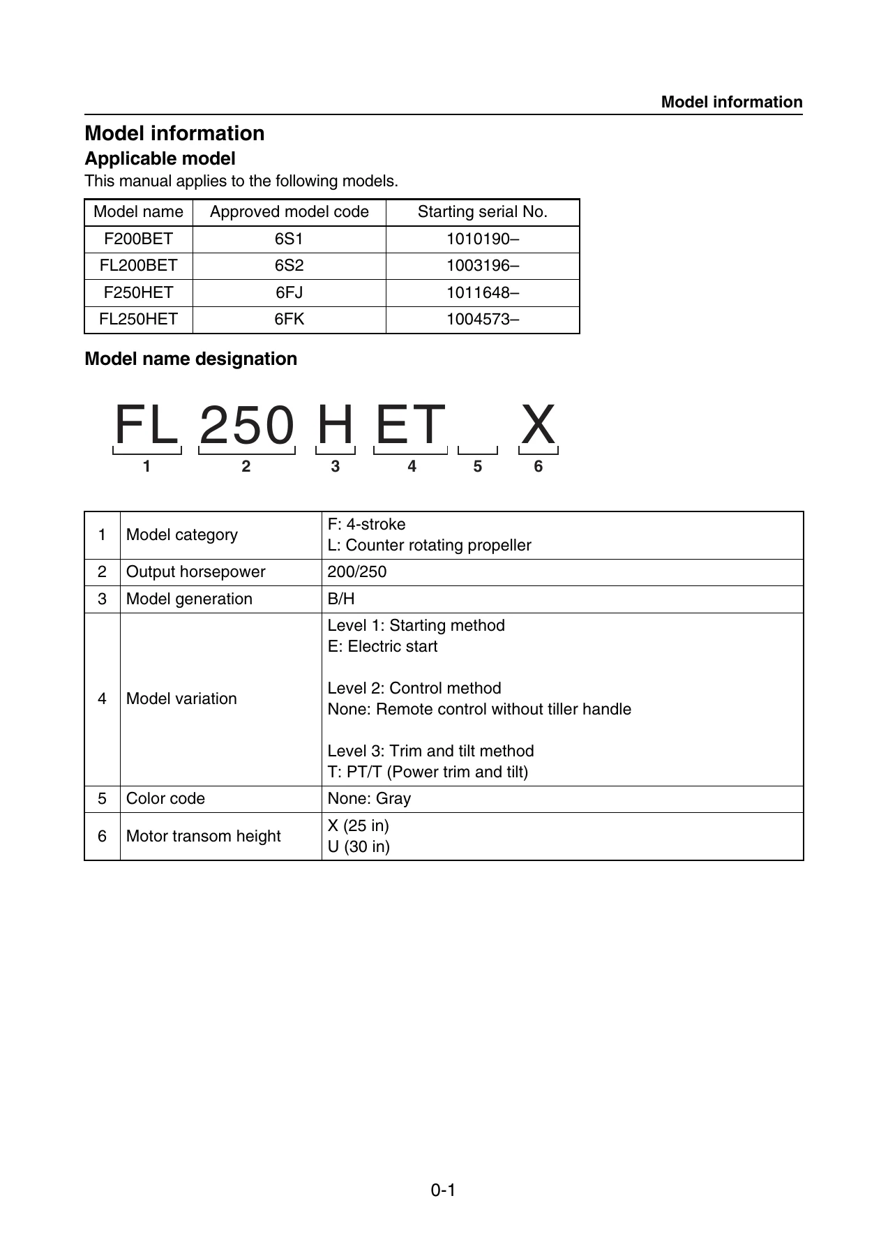
+Model informationp. 5
Applicable modelp. 5
Model name designationp. 5
General featurep. 6
+Important safety and service informationp. 7
Rotating partsp. 7
Hot partsp. 7
Electric shockp. 7
Propellerp. 7
Handling of gasolinep. 7
Ventilationp. 7
Self-protectionp. 7
Lifting outboard motorsp. 8
Handling of gas torchp. 8
Parts, lubricants, and sealantsp. 8
Handling of lubricants and sealantsp. 8
Special service toolsp. 9
Tightening torquep. 9
Non-reusable partsp. 9
Disassembly and assemblyp. 9
Disposal of used components and chemicalsp. 9
+How to use this manualp. 10
Manual formatp. 10
Conditions when testing and adjustingp. 11
Abbreviationp. 11
Color codep. 11
+Specified tightening torquep. 12
General tightening torquep. 12
+Symbolp. 13
Specification symbolp. 13
Lubricant, sealant, and thread locking agent symbolp. 13
Special service toolp. 15
+Specificationp. 19
Specification datap. 20
External dimensionsp. 20
Clamp bracket dimensionsp. 22
+Technical feature and descriptionp. 23
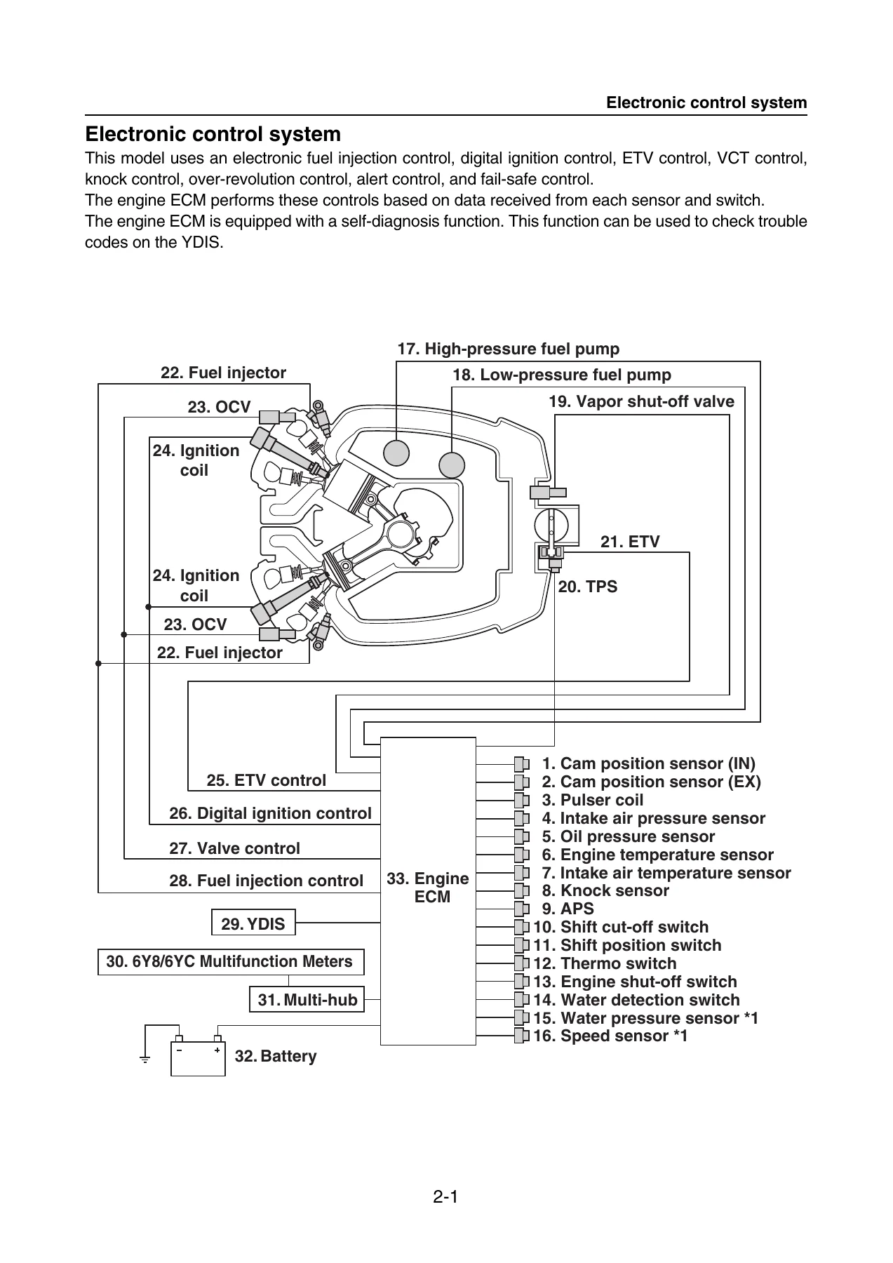
+Electronic control systemp. 24
Electrical componentsp. 26
Fail-safep. 28
+Fuse box and relayp. 30
Fuse boxp. 30
Self-diagnosis of power supply circuitp. 31
Trouble code detecting conditionsp. 31
+Serviceabilityp. 33
+Lower unitp. 34
Shift Dampener System (SDS)p. 34
+Fuel systemp. 35
+Lubrication systemp. 37
+Cooling systemp. 39
+Intake and exhaust systemp. 41
Intake and exhaust diagramp. 41
+Hose routingp. 42
Fuel hose and blowby hosep. 42
Pressure regulator hose, vapor gas hose, and intake air pressure sensor hosep. 43
Cooling water hosep. 44
+Rigging informationp. 45
+Important reminder on riggingp. 46
Outboard motor mounting instructionsp. 46
+Crate handlingp. 47
Crate top cover symbol descriptionp. 47
+Uncratingp. 48
+Rigging grommet mountingp. 49
Rigging grommet descriptionp. 49
Installing the battery cablep. 50
Installing the shift cablep. 50
Installing the throttle cablep. 51
Installing the main wire harnessp. 52
Installing the 6Y8/6YC multifunction meter harness (pigtail bus wire)p. 52
Installing the conventional gauge (6Y5/6Y7) harnessp. 53
Installing the rigging grommetp. 53
+Optional equipmentp. 54
Installing the isolator leadp. 54
Installing the twin engine tie-bar with steering cablep. 54
Battery installationp. 54
+Rigging recommendationp. 54
Battery cable lengthp. 54
Propeller selectionp. 55
+Troubleshootingp. 59
+YDISp. 60
Connecting the communication cablep. 60
ECM reprogrammingp. 62
+Outboard motor troubleshootingp. 63
Troubleshooting procedurep. 63
Troubleshooting the power unit using the YDISp. 63
Trouble code and checking stepp. 65
Troubleshooting procedure (trouble code not detected)p. 73
Troubleshooting the power unitp. 73
Troubleshooting the PTT unitp. 78
Troubleshooting the lower unitp. 79
+Electrical systemp. 80
+Electrical componentp. 82
Portp. 82
Starboardp. 83
Fuse holderp. 84
Rearp. 85
Topp. 86
Bottom cowlingp. 87
+Wire harness routingp. 88
Portp. 88
Starboardp. 90
Rearp. 92
Topp. 94
Bottom cowlingp. 96
ECM circuit diagramp. 98
ECM coupler layoutp. 101
+Checking the electrical componentp. 103
Using the YDISp. 103
Measuring the peak voltagep. 103
Using the digital testerp. 104
+Engine control unit and componentp. 104
Checking the main relayp. 104
Checking the engine ECM circuitp. 104
Checking the ETV and TPSp. 105
Checking the ETV motor relayp. 106
Checking the APSp. 106
Checking the cam position sensorp. 107
Checking the OCVp. 109
Checking the oil pressure sensorp. 110
+Fuel control unit and componentp. 111
Checking the water detection switchp. 111
Checking the fuel injectorp. 112
Checking the low-pressure fuel pump and high-pressure fuel pumpp. 113
Checking the high-pressure fuel pump relayp. 114
Checking the vapor shut-off valvep. 114
+Charging unit and componentp. 115
Checking the lighting coil (stator assembly)p. 115
Checking the Rectifier/Regulator/Isolatorp. 115
+Ignition unit and componentp. 116
Checking the ignition sparkp. 116
Checking the ignition coilp. 116
Checking the pulser coilp. 117
Checking the intake air temperature sensorp. 118
Checking the intake air pressure sensorp. 119
Checking the engine temperature sensorp. 120
Checking the thermo switchp. 120
Checking the knock sensorp. 121
Checking the shift cut-off switchp. 122
Checking the shift position switchp. 122
Checking the engine shut-off switchp. 123
+Starting unit and componentp. 124
Checking the starter relayp. 124
Checking the engine start switchp. 124
+Starter motorp. 125
Removing the starter motorp. 126
Disassembling the starter motorp. 126
Checking the starter motor pinionp. 128
Checking the armature (starter motor)p. 128
Checking the brush holderp. 129
Assembling the starter motorp. 129
Installing the starter motorp. 131
+6Y8/6YC Multifunction Meters sensorp. 132
Checking the water pressure sensorp. 132
Checking the speed sensorp. 132
+PTT systemp. 134
Checking the PTT relayp. 134
Checking the PTT switch (on bottom cowling)p. 135
Checking the trim sensorp. 136
+Fuel systemp. 137
+Fuel systemp. 139
Reducing the fuel pressurep. 139
Disconnecting the quick connectorp. 139
Measuring the fuel pressurep. 140
Checking the pressure regulatorp. 141
+Fuel filter assemblyp. 143
Removing the fuel filter assemblyp. 144
Checking the fuel filter assemblyp. 144
Checking the fuel filter elementp. 144
Checking the fuel cup assemblyp. 144
Checking the primer pumpp. 145
Assembling the fuel filter assemblyp. 145
Installing the fuel filter assemblyp. 145
+Intake manifoldp. 146
Checking the intake manifoldp. 147
Checking the intake air temperature sensorp. 147
Installing the intake manifoldp. 147
Installing the intake silencerp. 148
+Throttle bodyp. 150
Checking the canister check valvep. 151
Checking the vacuum hosep. 151
Installing the throttle body assemblyp. 151
+ETVp. 153
Checking the ETVp. 154
Checking the intake air pressure sensorp. 154
Checking the canisterp. 154
Installing the canister, ETV, and surge tankp. 154
+Low-pressure fuel pumpp. 156
Removing the low-pressure fuel pumpp. 157
Installing the low-pressure fuel pumpp. 157
+Vapor separatorp. 158
Draining the fuelp. 159
Removing the vapor separatorp. 159
Installing the vapor separatorp. 159
+Vapor separator and high-pressure fuel pumpp. 161
Checking the vapor separatorp. 162
Checking the check valvep. 162
Assembling the vapor separatorp. 163
+Fuel injectorp. 165
Removing the fuel injectorp. 166
Checking the fuel rail and fuel injectorp. 166
Checking the quick connectorp. 166
Installing the fuel injectorp. 167
+Power unitp. 169
+Power unit (check and adjustment)p. 172
Checking the compression pressurep. 172
Checking the oil pressurep. 172
Checking the pulser coil air gapp. 173
Checking the valve clearancep. 173
Adjusting the valve clearancep. 175
+Power unit assemblyp. 178
Removing the power unitp. 179
Installing the power unitp. 182
+Flywheel magnetop. 186
Removing the flywheel magnetop. 187
Installing the flywheel magnetop. 188
+Wire harnessp. 190
Installing the wire harnessp. 191
Fuse boxp. 196
+Junction boxp. 197
Checking the Rectifier/Regulator/Isolator anodep. 198
Installing the junction boxp. 198
Installing the Rectifier/Regulator/Isolatorp. 198
+Starter motor and APSp. 200
Engine ECMp. 202
+Timing beltp. 203
Removing the timing beltp. 204
Checking the timing beltp. 205
Installing the timing beltp. 205
+Cylinder head coverp. 208
Checking the spark plugp. 209
Installing the cylinder head coverp. 209
+Camshaftp. 211
Removing the driven sprocket and camshaftp. 212
Checking the sprocketp. 213
Checking the valve lifterp. 213
Checking the camshaftp. 213
Checking the camshaft journal oil clearancep. 214
Checking the camshaft journal outside diameter and camshaft journal inside diameterp. 215
Installing the camshaft and driven sprocketp. 216
+Exhaust coverp. 221
Removing the exhaust coverp. 222
Checking the exhaust cover anodep. 222
Installing the exhaust coverp. 222
+Cylinder headp. 224
Removing the cylinder headp. 226
Disassembling the cylinder headp. 226
Checking the cylinder headp. 227
Checking the valve springp. 227
Checking the valvep. 227
Checking the valve guidep. 228
Replacing the valve guidep. 229
Checking the valve seatp. 230
Refacing the valve seatp. 231
Checking the cylinder head anodep. 233
Assembling the cylinder headp. 233
Installing the cylinder headp. 235
+Cooling water coverp. 237
Removing the cooling water coverp. 238
Checking the cooling water cover anodep. 238
Installing the cooling water coverp. 238
+Crankcasep. 240
Removing the oil filter bracketp. 241
Removing the oil pumpp. 241
Removing the crankcase coverp. 241
Checking the oil pumpp. 241
Assembling the oil pumpp. 242
Installing the crankcase coverp. 243
Installing the oil pump assemblyp. 243
Installing the oil filter bracketp. 244
+Cylinder blockp. 246
Disassembling the cylinder blockp. 248
Checking the thermostatp. 249
Checking the piston diameterp. 250
Checking the cylinder borep. 250
Checking the piston clearancep. 250
Checking the piston ringp. 251
Checking the piston ring end gapp. 251
Checking the piston ring groovep. 252
Checking the piston ring side clearancep. 252
Checking the piston pin boss inside diameterp. 252
Checking the piston pin diameterp. 253
Checking the connecting rod small end inside diameter and big end inside diameterp. 253
Checking the connecting rod big end side clearancep. 254
Checking the crankshaftp. 254
Checking the crankcase boltp. 255
Checking the big end oil clearancep. 255
Selecting the crankshaft pin bearingp. 256
Checking the journal oil clearancep. 257
Selecting the crankshaft journal bearingp. 259
Crankshaft journal bearing selection tablep. 260
Checking the cylinder block anodep. 261
Assembling the cylinder blockp. 261
+Lower unitp. 266
+Propellerp. 269
Removing the propellerp. 270
Disassembling the propeller (Shift Dampener System [SDS] propeller)p. 270
Checking the propellerp. 270
Assembling the propeller (Shift Dampener System [SDS] propeller)p. 270
Installing the propellerp. 271
+Lower unitp. 272
Removing the lower unitp. 273
Checking the lower unit anodep. 273
Checking the lower unit for leakagep. 274
Installing the lower unitp. 274
+Extension (U-transom model)p. 276
Checking the extensionp. 277
+Water pump and shift rodp. 278
Removing the shift rodp. 279
Checking the water pumpp. 279
Checking the shift rodp. 279
Assembling the water pump housingp. 279
Installing the shift rodp. 280
Installing the water pumpp. 280
+Propeller shaft housing (regular rotation model)p. 282
Removing the propeller shaft housing assemblyp. 283
Disassembling the propeller shaft assemblyp. 283
Disassembling the propeller shaft housing assemblyp. 283
Checking the propeller shaftp. 284
Checking the dog clutchp. 285
Checking the propeller shaft housingp. 285
Checking the reverse gearp. 285
Assembling the propeller shaft assemblyp. 285
Assembling the propeller shaft housing assemblyp. 286
Installing the propeller shaft housing assemblyp. 287
+Drive shaft and lower case (regular rotation model)p. 289
Removing the drive shaftp. 290
Disassembling the drive shaft housingp. 290
Disassembling the forward gearp. 291
Disassembling the lower casep. 291
Checking the pinionp. 292
Checking the forward gearp. 292
Checking the drive shaftp. 292
Checking the lower casep. 292
Assembling the lower casep. 292
Assembling the forward gearp. 293
Assembling the drive shaft housingp. 294
Installing the forward gearp. 294
Installing the drive shaftp. 295
+Shimming (regular rotation model)p. 296
Shimming workflowp. 296
Shimming check sheetp. 297
Measuring the forward gear backlash and reverse gear backlash before disassemblyp. 299
Shimming procedurep. 303
Shim locationp. 303
Selecting the pinion shim (T3)p. 304
Selecting the propeller shaft shim (T4)p. 307
Measuring the forward gear backlashp. 307
Adjusting the forward gear shim thickness (T1)p. 308
Measuring the reverse gear backlashp. 310
Adjusting the reverse gear shim thickness (T2)p. 310
+Propeller shaft housing (counter rotation model)p. 312
Removing the propeller shaft housing assemblyp. 313
Disassembling the propeller shaft assemblyp. 313
Disassembling the propeller shaft housing assemblyp. 313
Disassembling the forward gearp. 314
Checking the propeller shaftp. 314
Checking the dog clutchp. 314
Checking the propeller shaft housingp. 315
Checking the forward gearp. 315
Assembling the propeller shaft housing and forward gearp. 315
Installing the propeller shaft housing assemblyp. 317
+Drive shaft and lower case (counter rotation model)p. 319
Removing the drive shaftp. 320
Disassembling the drive shaft housingp. 320
Disassembling the reverse gearp. 320
Disassembling the lower casep. 320
Checking the pinionp. 320
Checking the reverse gearp. 320
Checking the drive shaftp. 320
Checking the lower casep. 320
Assembling the lower casep. 321
Assembling the reverse gearp. 322
Assembling the drive shaft housingp. 322
Installing the reverse gearp. 322
Installing the drive shaftp. 322
+Shimming (counter rotation model)p. 323
Shimming workflowp. 323
Shimming check sheetp. 324
Measuring the forward gear backlash and reverse gear backlash before disassemblyp. 326
Shimming procedurep. 330
Shim locationp. 330
Selecting the pinion shim (T3)p. 331
Selecting the propeller shaft shim (T4)p. 331
Measuring the forward gear backlashp. 332
Adjusting the forward gear shim thickness (T2)p. 332
Measuring the reverse gear backlashp. 334
Adjusting the reverse gear shim thickness (T1)p. 334
+Bracket unitp. 337
+Shift rod and shift bracketp. 339
Assembling the shift bracketp. 340
Installing the shift rod and shift bracketp. 341
+PTT switch and cowling lock leverp. 342
Installing the flushing hose and cooling water hosep. 344
Installing the cowling lock leverp. 345
Bottom cowlingp. 346
+Upper case and mountsp. 347
Removing the upper casep. 348
Installing the upper casep. 348
+Upper casep. 350
Disassembling the upper casep. 351
Checking the drive shaft bushingp. 351
Checking the PCVp. 351
Assembling the upper casep. 351
+Oil pan and exhaust manifoldp. 353
Checking the oil pan and exhaust manifoldp. 354
Checking the oil strainerp. 354
Assembling the oil pan and exhaust manifoldp. 354
+Steering armp. 356
Removing the steering armp. 357
Installing the steering armp. 357
+Clamp bracket and swivel bracketp. 359
Removing the clamp bracketp. 360
Checking the clamp bracket anodep. 360
Installing the clamp bracketp. 360
Adjusting the trim sensor camp. 362
+PTT unitp. 363
Removing the PTT unitp. 364
Checking the hydraulic pressurep. 364
Bleeding the PTT unitp. 367
Installing the PTT unitp. 368
+PTT motorp. 370
Removing the reservoirp. 371
Disassembling the PTT motorp. 371
Checking the PTT motorp. 371
Checking the brushp. 372
Checking the reservoirp. 372
Checking the filterp. 372
Assembling the PTT motorp. 372
Installing the reservoirp. 373
Installing the PTT motorp. 373
+PTT gear pumpp. 375
Disassembling the gear pump assemblyp. 377
Checking the gear pumpp. 377
Checking the gear pump housingp. 377
Checking the filterp. 377
Assembling the gear pump assemblyp. 377
Installing the gear pump assemblyp. 379
+PTT cylinderp. 380
Removing the tilt ramp. 381
Removing the trim ramp. 381
Disassembling the tilt ramp. 381
Checking the tilt cylinder and trim cylinderp. 382
Checking the absorber valvep. 382
Assembling the tilt ramp. 382
Assembling the trim ramp. 383
Installing the tilt cylinderp. 384
Installing the trim ramp. 384
Installing the tilt ramp. 385
+Maintenancep. 386
+Outlinep. 387
Maintenance interval chart 1p. 387
Maintenance interval chart 2p. 389
+Predelivery checkp. 390
Checking the engine oil levelp. 393
Checking the batteryp. 393
Checking the cooling water pilot holep. 394
Checking the gear oil levelp. 394
Checking the outboard motor mounting heightp. 395
+General periodic maintenancep. 396
Checking the cooling water inletp. 399
Checking the engine idle speedp. 399
Changing the engine oil using an oil changerp. 399
Changing the engine oil by removing the drain boltp. 400
Replacing the oil filterp. 402
Changing the gear oilp. 403
Greasing pointsp. 404
Greasing the clamp bracket bolt (through tube)p. 405
Checking the PTT fluid levelp. 406
Checking the cowling lock leverp. 406
+Appendixp. 408
+Wiring diagramp. 416
How to use the wiring diagramp. 416
Engine control unitp. 418
Fuel unitp. 419
Ignition unitp. 420
Charging unit, starting unit, and PTT unitp. 421
Control unitp. 422
Rectifier/Regulator/Isolator continuity tablep. 423
+Shim selection table and chart (regular rotation model)p. 424
Pinion shim (T3) selection tablep. 424
Forward gear shim (T1) selection chartp. 425
Reverse gear shim (T2) selection chartp. 425
+Shim selection table and chart (counter rotation model)p. 426
Pinion shim (T3) selection tablep. 426
Propeller shaft shim (T4) selection tablep. 426
Forward gear shim (T2) selection chartp. 427
Reverse gear shim (T1) selection chartp. 427
- Engine diagnosis – Read trouble codes through the YDIS, interpret fail-safe conditions, and follow the troubleshooting charts for the power unit, PTT unit, and lower unit.
- Power unit repair – Remove and install the power unit, service the flywheel magneto and stator, replace the timing belt, adjust valve clearance with the shimless valve lifter system, remove and install camshafts, service the cylinder head, and rebuild the cylinder block with correct bearing selections.
- Fuel system service – Test fuel pressure, service the pressure regulator, replace the fuel filter element, remove and install fuel injectors, service the vapor separator, check the high-pressure and low-pressure fuel pumps, and work with the quick connectors safely.
- Electrical system work – Test the ECM circuit, ETV and TPS, APS, cam position sensors, OCV, oil pressure sensor, water detection switch, fuel injector, ignition coil, pulser coil, intake air temperature and pressure sensors, engine temperature sensor, thermo switch, knock sensor, shift cut-off and shift position switches, and the starter motor.
- Lower unit overhaul – Disassemble and reassemble the lower unit, replace the water pump impeller and housing, service the propeller shaft housing, check and adjust gear backlash using shim selection tables, and rebuild both regular and counter rotation gearcases.
- Bracket and PTT service – Remove and install the PTT unit, check hydraulic pressure, bleed the system, disassemble and assemble the PTT motor, service the gear pump, rebuild the tilt and trim rams, and adjust the trim sensor.
- Maintenance – Follow the maintenance interval charts for 20-hour, 100-hour, 300-hour, and 500-hour service, change engine oil and gear oil, replace the oil filter, grease all lubrication points, and perform predelivery checks.
Why This Manual Matters
The Yamaha F200B, FL200B, F250H, and FL250H are complex 4-stroke outboards with electronic fuel injection, variable camshaft timing, electronic throttle valve, and a sophisticated ECM-controlled fail-safe system. Working on these engines without the correct specifications and procedures risks incorrect assembly, damaged components, or unsafe operation. This manual provides the exact tightening torques, oil clearances, shim selection tables, backlash specifications, and diagnostic trouble code charts that Yamaha specifies for these models. The exploded diagrams and assembly drawings show the correct order of removal and installation, including the marked alignment points for the timing belt, camshaft dowel pins, and VCT assemblies. The shimming chapters for the lower unit include the measurement procedures and selection charts needed to set forward gear backlash, reverse gear backlash, pinion height, and propeller shaft free play to factory specification.
Delivery
This Yamaha F200B FL200B F250H FL250H 4-Stroke Outboard Service Manual is delivered as an instant PDF download after purchase. There is no shipping and no waiting for a physical book. The file works on any device that can open a PDF – laptop, tablet, or smartphone – and you can print the pages you need for the workshop. Whether you are a Yamaha dealer technician, a marine mechanic, or an owner doing your own maintenance and repairs, this manual gives you the complete factory service information in a single document.
Reviews
There are no reviews yet.