
Yanmar B110W Wheel Excavator Service Manual 2017 Full Workshop Repair Guide
Original price was: $39.95.$24.95Current price is: $24.95.
Complete 796-page workshop service manual for the Yanmar B110W wheel excavator, covering the DEUTZ TCD 3.6 L4 engine, hydraulics, electrics, maintenance, diagnosis and repair procedures.
Description
Yanmar B110W Wheel Excavator Service Manual — 2017 Edition
This is the complete service manual for the Yanmar B110W wheel excavator, published in 2017. Across 796 pages it documents the full machine — the DEUTZ TCD 3.6 L4 diesel engine, the hydraulic travel and working systems, the electrical architecture, maintenance schedules, setting instructions and repair procedures. Everything is written for the technician who actually works on the machine, not for a showroom brochure.
If you own, service or repair a B110W, this Yanmar B110W Wheel Excavator Service Manual is the reference you keep on the workshop laptop. It is the same document a trained dealer technician would work from — covering everything from tightening torques for pistons and guide bushings to the full diagnostic flash-code procedure for the engine control unit.
File Details
- Manual type: Service / Workshop Manual
- Machine: Yanmar B110W Wheel Excavator
- Engine: DEUTZ TCD 3.6 L4 (Tier 4 final), TD 3.6 L4
- Publication year: 2017
- Language: English
- Page count: 796
- File format: PDF
- Document sections: 12 main groups (01 through 12)
Chapters Covered in the Yanmar B110W Service Manual
- 01 General — foreword and user instructions; safety and accident prevention; symbol and hazard descriptions; mandatory signs; safety signs; tightening torques for pistons or piston nuts; tightening torques for guide bushings; pictograms; measuring connections; units and conversion tables.
- 02 Technical Data — drive motor (DEUTZ TCD 3.6 L4 Tier 4 final); electrical system; working cycles and cycle times; pressure and set values for traveling; steering system; rotation drive (slewing drive); fan drive with reversing; working hydraulics; travel drive; brake; axles; travel range; lubricants; fluid capacities; drift values.
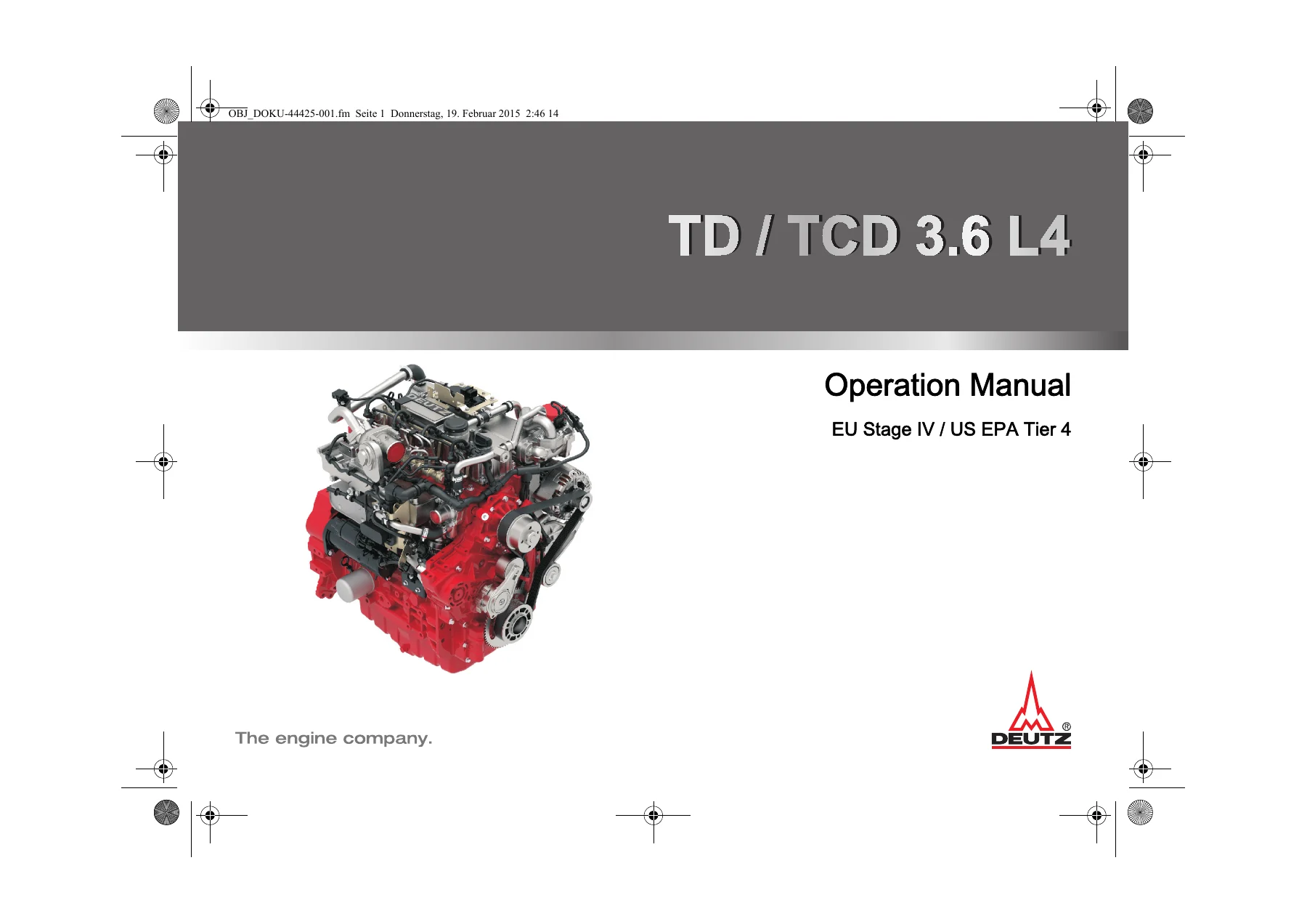
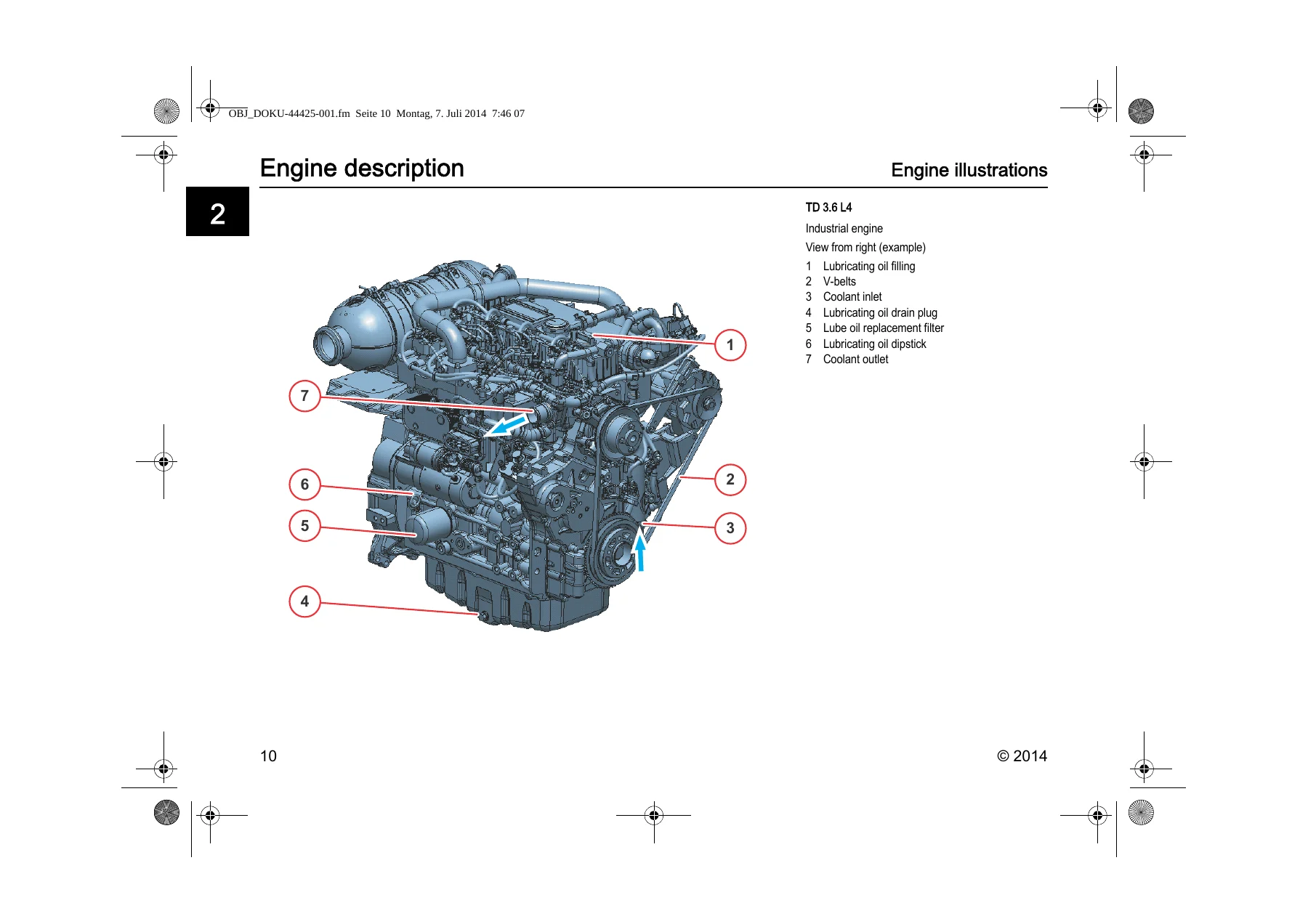
- 03 Diesel Engine — DEUTZ TD/TCD 3.6 L4 operating manual and workshop manual; bleeding the fuel system; safety precautions; engine type designation; emissions legislation; rating plate location; engine serial number; cylinder numbering; lubricating oil system; fuel schematic; coolant schematic; external exhaust gas recirculation; exhaust gas aftertreatment; electronic engine control; starting; shutting off; operating media; permissible fuels; coolants; AdBlue; maintenance schedules (E10, E20, E30, E40, E50, E70); servicing and maintenance work; faults and remedies; engine protection function; diagnosis button; flash codes.
- 04 Hydraulics — hydraulic circuit diagrams for articulated boom standard and with options (serial ranges 0100–0156 and 0157 and up).
- 05 Setting Instructions — general setting instructions; Hydromatik tightening values; travel hydraulics (A4VG 90 DA travel pump, A6VM 107 DA travel motor); control valve SX14; control valve DPX100/6+1; pilot control unit; working hydraulics; work variable displacement pump A11VO95LR3S.
- 06 Function Description — pilot control device 4TH6 with handle options.
- 07 Electrics — cable colors; vehicle electrics; monitoring displays; relay assignment; fuse assignment; structural diagram for diesel engine control unit; structural diagram for fan control system; structural diagram for electrical components; diagnostics and programming connection; CAN structure; fuse legend; relay legend; switch overview; fault indication on keypad and display; warning buzzer behavior.
- 08 Maintenance — specification for fuels, lubricants and coolants; inspection plan; work to be carried out by trained dealer service personnel.
- 09 Operation — keypad operation; instructions for using the combo-tool (display); engine monitoring icons; machine monitoring icons; error indicator; menu control; submenus for machine functions, machine options, machine adjustments, fan control, air-conditioning control, rear view camera, diagnostics/service, basic settings; overload warning.
- 10 Options — pressure setting for front dozer blade; exhaust gas after-treatment system (DPF replacement); auto-idling system hydraulics and electrics diagrams.
- 11 Repair Instructions — fitting hydraulic screw connections; adhesive kit for cab windows; tilting the cab.
- 12 Diagnosis / Tools — special tools (purchased parts); diagnostics and programming port; hydraulic test kit; digital multimeter; magnetic field tester; hydraulic testing fittings; oil service tool; pressure and vacuum pump; hydraulic hand pump.
What This Service Manual Gives You
The Yanmar B110W Wheel Excavator Service Manual is structured as a full workshop reference, not a collection of extracts. It opens with the general safety and accident-prevention material that governs every job on the machine — hazard zones, stability limits, safety distances from overhead and underground power lines, hoisting rules and the correct handling of hydraulic and electrical systems. From there it moves into the hard numbers: the complete technical data section for the DEUTZ TCD 3.6 L4 engine, the pressures and set values for the travel drive, steering, slewing, working hydraulics and brake circuits, plus fluid capacities and lubricant specifications.
The engine chapter is built around the DEUTZ TD/TCD 3.6 L4 documentation and covers the full service cycle — fuel system bleeding, lubricating oil system, coolant schematic, exhaust gas recirculation, exhaust aftertreatment (DOC, DPF, SCR with AdBlue), electronic engine control, start and shut-off procedures, operating media and the complete maintenance schedule. The fault tables and flash-code diagnostics let you trace problems methodically instead of guessing.
For hydraulics, the manual provides the circuit diagrams for the articulated boom in both standard and optioned configurations, split by serial number, so you always work from the drawing that matches the machine in front of you. The setting-instruction chapter then gives the adjustment procedures for the travel pump, travel motor, control valves SX14 and DPX100/6+1, pilot control unit and the A11VO95LR3S work pump. Each adjustment is tied to a measured value and a tightening or rotation setting — no approximate work.
The electrical section is unusually thorough for a machine of this class. It includes the structural diagrams for the diesel engine control unit, the fan control unit and the main electrical components, the CAN bus structure, fuse and relay legends, switch overview, diagnostic and programming connections, and the full fault-indication behaviour of the keypad, display and warning buzzer. The maintenance chapter sets out the inspection plan by operating hours and by calendar interval, so you can build a service schedule that matches the manual’s own criteria.
The options chapter covers the front dozer blade pressure setting, the diesel particle filter replacement procedure for the exhaust aftertreatment system, and the auto-idling system with both its hydraulic and electrical diagrams. The repair-instructions chapter explains cutting-ring fitting to DIN 3859-2, the adhesive kit for cab windows, and the complete procedure for tilting the cab — including the safety bar requirements and the warning not to work underneath a tilted cab without it mounted.
Why This Manual Matters for B110W Work
Wheel excavators of this class are hydraulic-heavy machines, and the most expensive failures come from working without the correct pressures, torques or bleeding procedures. The Yanmar B110W service manual removes that risk. Every pressure value is stated with a tolerance, every tightening torque is given with the type of mounting, and every adjustment procedure is tied to a specific measurement condition (hydraulic oil temperature 50–60 °C, engine at specified speed).
The DEUTZ TCD 3.6 L4 engine in this machine is a Tier 4 final unit with DOC, DPF and SCR aftertreatment. That means regeneration procedures, AdBlue quality and dosing, and the standstill regeneration process are all part of normal ownership. The manual covers the warning strategy in detail — the difference between heat mode, standstill regeneration request and the various warning levels — so you can act before the engine control unit forces a power reduction or a filter change.
For the hydraulic system, the setting instructions alone justify this manual. The travel pump A4VG 90 DA, travel motor A6VM 107 DA, control valves SX14 and DPX100/6+1, pilot control unit and work pump A11VO95LR3S all have specific adjustment sequences. Getting the neutral position, start-up speed, stall speed, pressure cut-off, adjustment start and inching settings right is what separates a machine that works smoothly from one that overheats, lugs or loses power. The manual gives the sequence and the target values.
For electrical diagnosis, the CAN structure, fuse and relay legends, and the flash-code interpretation are all in one place. The engine control unit’s error lamp behaviour — continuous light versus flashing, and what each means for whether you can continue operating — is documented alongside the override switch procedure for moving the machine in an emergency.
Finally, the 796-page scope means this manual covers the B110W as a complete machine, not just as an engine or a hydraulic system. Cab tilting for access, hydraulic hose and fitting assembly to DIN standards, cab window bonding, central lubrication, comfort seat, telematics connector, rear view camera and the full keypad/display menu structure are all included.
Get Instant Access
IMAGES PREVIEW
The Yanmar B110W Wheel Excavator Service Manual is delivered as an instant PDF download — no shipping, no waiting, no physical binder to lose. You can open it on a laptop, tablet or phone in the workshop, search within it using your PDF reader, and print individual pages or whole chapters as needed. Whether you are a dealer technician, an independent workshop, or an owner who prefers to do the maintenance personally, this is the full workshop reference for the B110W in one file.

Reviews
There are no reviews yet.